Grammar
Source Link
Simon Fitch
  • 47.3k
  • 3
  • 25
  • 135

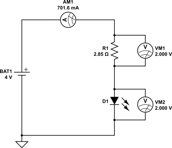
LetsLet's say the battery is 4.0V, the LED drops 2V and the current through the LED is 700mA.

You have this:
schematic

simulate this circuit – Schematic created using CircuitLab

Given everything you've said about the LED and battery, these are the conditions that must be present. For the current to be 700mA, and the voltage across the LED to be 2V, then naturally the remaining 2V must be across the resistor. You could have predicted the necessary resistance R1, using Ohm's law:

$$ R_1 = \frac{V_{BAT1}-V_{D1}}{I} = \frac{2V}{0.7A} = 2.85\Omega $$

There is no other way for this equilibrium to occur, R1 must be 2.85Ω.

Don't forget, that resistance must include any additional resistance around the loop, such as wire resistance, contact resistance introduced by crocodile clips, or plugs, or breadboard connections.

Look at the power being dissipated in R1:

$$ P_{R1} = {{I_{R1}}^2R_1} = (700mA)^2 \times 2.85\Omega = 1.4W $$

R1 is going to get hot, 1.4W is easily enough to burn when you touch it, unless you take measures to cool it somehow.

The LED is dead now because you placed 4V across an LED rated for 2V, with no resistor present to limit current as R1 does in the above system. Current skyrocketed well beyond 700mA (probably many amps), and melted the poor thing.

I suspect that your ammeter's resistance (the so-called "burden" resistance, a resistance that current flows through to develop a voltage, that a voltmeter can measure and convert to and display as current, using Ohm,'s law) is significant compared to the required total resistance of 2.85Ω. With the ammeter in place, along with all the other unintended connection resistances around the loop, total resistance rises to well above 2.85Ω, and that's why you couldn't reach the desired 700mA during current measurement.


I wanted to add that we almost never use resistors in such high-current LED applications. With such a low overhead of \$V_{BAT1}-V_{LED} = 2V\$, very small resistances are required, comparable with other unintentional resistances around the loop. It's difficult to obtain the exact resistance required when the value is so small. For this reason, we usually employ active current regulation, to obtain an exact current flow, which can be achieved with a transistor or DC-DC converter.

Lets say the battery is 4.0V, the LED drops 2V and the current through the LED is 700mA.

You have this:

schematic

simulate this circuit – Schematic created using CircuitLab

Given everything you've said about the LED and battery, these are the conditions that must be present. For the current to be 700mA, and the voltage across the LED to be 2V, then naturally the remaining 2V must be across the resistor. You could have predicted the necessary resistance R1, using Ohm's law:

$$ R_1 = \frac{V_{BAT1}-V_{D1}}{I} = \frac{2V}{0.7A} = 2.85\Omega $$

There is no other way for this equilibrium to occur, R1 must be 2.85Ω.

Don't forget, that resistance must include any additional resistance around the loop, such as wire resistance, contact resistance introduced by crocodile clips, or plugs, or breadboard connections.

Look at the power being dissipated in R1:

$$ P_{R1} = {{I_{R1}}^2R_1} = (700mA)^2 \times 2.85\Omega = 1.4W $$

R1 is going to get hot, 1.4W is easily enough to burn when you touch it, unless you take measures to cool it somehow.

The LED is dead now because you placed 4V across an LED rated for 2V, with no resistor present to limit current as R1 does in the above system. Current skyrocketed well beyond 700mA (probably many amps), and melted the poor thing.

I suspect that your ammeter's resistance (the so-called "burden" resistance, a resistance that current flows through to develop a voltage, that a voltmeter can measure and convert to and display as current, using Ohm,'s law) is significant compared to the required total resistance of 2.85Ω. With the ammeter in place, along with all the other unintended connection resistances around the loop, total resistance rises to well above 2.85Ω, and that's why you couldn't reach the desired 700mA during current measurement.


I wanted to add that we almost never use resistors in such high-current LED applications. With such a low overhead of \$V_{BAT1}-V_{LED} = 2V\$, very small resistances are required, comparable with other unintentional resistances around the loop. It's difficult to obtain the exact resistance required when the value is so small. For this reason, we usually employ active current regulation, to obtain an exact current flow, which can be achieved with a transistor or DC-DC converter.

Let's say the battery is 4.0V, the LED drops 2V and the current through the LED is 700mA.

You have this:

schematic

simulate this circuit – Schematic created using CircuitLab

Given everything you've said about the LED and battery, these are the conditions that must be present. For the current to be 700mA, and the voltage across the LED to be 2V, then naturally the remaining 2V must be across the resistor. You could have predicted the necessary resistance R1, using Ohm's law:

$$ R_1 = \frac{V_{BAT1}-V_{D1}}{I} = \frac{2V}{0.7A} = 2.85\Omega $$

There is no other way for this equilibrium to occur, R1 must be 2.85Ω.

Don't forget, that resistance must include any additional resistance around the loop, such as wire resistance, contact resistance introduced by crocodile clips, or plugs, or breadboard connections.

Look at the power being dissipated in R1:

$$ P_{R1} = {{I_{R1}}^2R_1} = (700mA)^2 \times 2.85\Omega = 1.4W $$

R1 is going to get hot, 1.4W is easily enough to burn when you touch it, unless you take measures to cool it somehow.

The LED is dead now because you placed 4V across an LED rated for 2V, with no resistor present to limit current as R1 does in the above system. Current skyrocketed well beyond 700mA (probably many amps), and melted the poor thing.

I suspect that your ammeter's resistance (the so-called "burden" resistance, a resistance that current flows through to develop a voltage, that a voltmeter can measure and convert to and display as current, using Ohm,'s law) is significant compared to the required total resistance of 2.85Ω. With the ammeter in place, along with all the other unintended connection resistances around the loop, total resistance rises to well above 2.85Ω, and that's why you couldn't reach the desired 700mA during current measurement.


I wanted to add that we almost never use resistors in such high-current LED applications. With such a low overhead of \$V_{BAT1}-V_{LED} = 2V\$, very small resistances are required, comparable with other unintentional resistances around the loop. It's difficult to obtain the exact resistance required when the value is so small. For this reason, we usually employ active current regulation, to obtain an exact current flow, which can be achieved with a transistor or DC-DC converter.

Address active current regulation
Source Link
Simon Fitch
  • 47.3k
  • 3
  • 25
  • 135

Lets say the battery is 4.0V, the LED drops 2V and the current through the LED is 700mA.

You have this:

schematic

simulate this circuit – Schematic created using CircuitLab

Given everything you've said about the LED and battery, these are the conditions that must be present. For the current to be 700mA, and the voltage across the LED to be 2V, then naturally the remaining 2V must be across the resistor. You could have predicted the necessary resistance R1, using Ohm's law:

$$ R_1 = \frac{V_{BAT1}-V_{D1}}{I} = \frac{2V}{0.7A} = 2.85\Omega $$

There is no other way for this equilibrium to occur, R1 must be 2.85Ω.

Don't forget, that resistance must include any additional resistance around the loop, such as wire resistance, contact resistance introduced by crocodile clips, or plugs, or breadboard connections.

Look at the power being dissipated in R1:

$$ P_{R1} = {{I_{R1}}^2R_1} = (700mA)^2 \times 2.85\Omega = 1.4W $$

R1 is going to get hot, 1.4W is easily enough to burn when you touch it, unless you take measures to cool it somehow.

The LED is dead now because you placed 4V across an LED rated for 2V, with no resistor present to limit current as R1 does in the above system. Current skyrocketed well beyond 700mA (probably many amps), and melted the poor thing.

I suspect that your ammeter's resistance (the so-called "burden" resistance, a resistance that current flows through to develop a voltage, that a voltmeter can measure and convert to and display as current, using Ohm,'s law) is significant compared to the required total resistance of 2.85Ω. With the ammeter in place, along with all the other unintended connection resistances around the loop, total resistance rises to well above 2.85Ω, and that's why you couldn't reach the desired 700mA during current measurement.


I wanted to add that we almost never use resistors in such high-current LED applications. With such a low overhead of \$V_{BAT1}-V_{LED} = 2V\$, very small resistances are required, comparable with other unintentional resistances around the loop. It's difficult to obtain the exact resistance required when the value is so small. For this reason, we usually employ active current regulation, to obtain an exact current flow, which can be achieved with a transistor or DC-DC converter.

Lets say the battery is 4.0V, the LED drops 2V and the current through the LED is 700mA.

You have this:

schematic

simulate this circuit – Schematic created using CircuitLab

Given everything you've said about the LED and battery, these are the conditions that must be present. For the current to be 700mA, and the voltage across the LED to be 2V, then naturally the remaining 2V must be across the resistor. You could have predicted the necessary resistance R1, using Ohm's law:

$$ R_1 = \frac{V_{BAT1}-V_{D1}}{I} = \frac{2V}{0.7A} = 2.85\Omega $$

There is no other way for this equilibrium to occur, R1 must be 2.85Ω.

Don't forget, that resistance must include any additional resistance around the loop, such as wire resistance, contact resistance introduced by crocodile clips, or plugs, or breadboard connections.

Look at the power being dissipated in R1:

$$ P_{R1} = {{I_{R1}}^2R_1} = (700mA)^2 \times 2.85\Omega = 1.4W $$

R1 is going to get hot, 1.4W is easily enough to burn when you touch it, unless you take measures to cool it somehow.

The LED is dead now because you placed 4V across an LED rated for 2V, with no resistor present to limit current as R1 does in the above system. Current skyrocketed well beyond 700mA (probably many amps), and melted the poor thing.

I suspect that your ammeter's resistance (the so-called "burden" resistance, a resistance that current flows through to develop a voltage, that a voltmeter can measure and convert to and display as current, using Ohm,'s law) is significant compared to the required total resistance of 2.85Ω. With the ammeter in place, along with all the other unintended connection resistances around the loop, total resistance rises to well above 2.85Ω, and that's why you couldn't reach the desired 700mA during current measurement.


I wanted to add that we almost never use resistors in such high-current LED applications. With such a low overhead of \$V_{BAT1}-V_{LED} = 2V\$, very small resistances are required, comparable with other unintentional resistances around the loop. It's difficult to obtain the exact resistance required when the value is so small. For this reason, we usually employ active current regulation, to obtain an exact current flow, which can be achieved with a transistor or DC-DC converter.

deleted 21 characters in body
Source Link
Simon Fitch
  • 47.3k
  • 3
  • 25
  • 135

Lets say the battery is 4.0V, the LED drops 2V and the current through the LED is 700mA.

You have this:

schematic

simulate this circuit – Schematic created using CircuitLab

Given everything you've said about the LED and battery, these are the conditions that must be present. For the current to be 700mA, and the voltage across the LED to be 2V, then naturally the remaining 2V must be across the resistor. You could have predicted the necessary resistance R1, using Ohm's law:

$$ R_1 = \frac{V_{BAT1}-V_{D1}}{I} = \frac{2V}{0.7A} = 2.85\Omega $$

There is no other way for this equilibrium to occur, R1 must be 2.85Ω.

Don't forget, that resistance must include any additional resistance around the loop, such as wire resistance, contact resistance introduced by crocodile clips, or plugs, or breadboard connections.

Look at the power being dissipated in R1:

$$ P_{R1} = {{I_{R1}}^2R_1} = (700mA)^2 \times 2.85\Omega = 1.4W $$

Of course R1 is going to get hot, 1.4W is easily enough to burn when you touch it, unless you take measures to cool that resistorit somehow.

The LED is dead now because you placed 4V across an LED rated for 2V, with no resistor present to limit current as R1 does in the above system. Current skyrocketed well beyond 700mA (probably many amps), and melted the poor thing.

I suspect that your ammeter's resistance (the so-called "burden" resistance, a resistance that current flows through to develop a voltage, that a voltmeter can measure and convert to and display as current, using Ohm,'s law) is significant compared to the required total resistance of 2.85Ω. With the ammeter in place, along with all the other unintended connection resistances around the loop, total resistance rises to well above 2.85Ω, and that's why you couldn't reach the desired 700mA during current measurement.

Lets say the battery is 4.0V, the LED drops 2V and the current through the LED is 700mA.

You have this:

schematic

simulate this circuit – Schematic created using CircuitLab

Given everything you've said about the LED and battery, these are the conditions that must be present. For the current to be 700mA, and the voltage across the LED to be 2V, then naturally the remaining 2V must be across the resistor. You could have predicted the necessary resistance R1, using Ohm's law:

$$ R_1 = \frac{V_{BAT1}-V_{D1}}{I} = \frac{2V}{0.7A} = 2.85\Omega $$

There is no other way for this equilibrium to occur, R1 must be 2.85Ω.

Don't forget, that resistance must include any additional resistance around the loop, such as wire resistance, contact resistance introduced by crocodile clips, or plugs, or breadboard connections.

Look at the power being dissipated in R1:

$$ P_{R1} = {{I_{R1}}^2R_1} = (700mA)^2 \times 2.85\Omega = 1.4W $$

Of course R1 is going to get hot, 1.4W is easily enough to burn when you touch it, unless you take measures to cool that resistor somehow.

The LED is dead now because you placed 4V across an LED rated for 2V, with no resistor present to limit current as R1 does in the above system. Current skyrocketed well beyond 700mA (probably many amps), and melted the poor thing.

I suspect that your ammeter's resistance (the so-called "burden" resistance, a resistance that current flows through to develop a voltage, that a voltmeter can measure and convert to and display as current, using Ohm,'s law) is significant compared to the required total resistance of 2.85Ω. With the ammeter in place, along with all the other unintended connection resistances around the loop, total resistance rises to well above 2.85Ω, and that's why you couldn't reach the desired 700mA during current measurement.

Lets say the battery is 4.0V, the LED drops 2V and the current through the LED is 700mA.

You have this:

schematic

simulate this circuit – Schematic created using CircuitLab

Given everything you've said about the LED and battery, these are the conditions that must be present. For the current to be 700mA, and the voltage across the LED to be 2V, then naturally the remaining 2V must be across the resistor. You could have predicted the necessary resistance R1, using Ohm's law:

$$ R_1 = \frac{V_{BAT1}-V_{D1}}{I} = \frac{2V}{0.7A} = 2.85\Omega $$

There is no other way for this equilibrium to occur, R1 must be 2.85Ω.

Don't forget, that resistance must include any additional resistance around the loop, such as wire resistance, contact resistance introduced by crocodile clips, or plugs, or breadboard connections.

Look at the power being dissipated in R1:

$$ P_{R1} = {{I_{R1}}^2R_1} = (700mA)^2 \times 2.85\Omega = 1.4W $$

R1 is going to get hot, 1.4W is easily enough to burn when you touch it, unless you take measures to cool it somehow.

The LED is dead now because you placed 4V across an LED rated for 2V, with no resistor present to limit current as R1 does in the above system. Current skyrocketed well beyond 700mA (probably many amps), and melted the poor thing.

I suspect that your ammeter's resistance (the so-called "burden" resistance, a resistance that current flows through to develop a voltage, that a voltmeter can measure and convert to and display as current, using Ohm,'s law) is significant compared to the required total resistance of 2.85Ω. With the ammeter in place, along with all the other unintended connection resistances around the loop, total resistance rises to well above 2.85Ω, and that's why you couldn't reach the desired 700mA during current measurement.

Source Link
Simon Fitch
  • 47.3k
  • 3
  • 25
  • 135
Loading