added more answer based on clarified question
Source Link
Jon Watte
  • 5.8k
  • 27
  • 37

I find that a convenient way of getting a lot of LEDs for a little money is flexible LED strips. You can put soft diffusing plastic on top of the strips to make the light more even.

You only need the Arduino for driving the score display. Build the LEDs into common-anode assemblies, one per digit, and switch the anode with a P-channel MOSFET and the cathodes with N-channel MOSFETs. You need six P-channel MOSFETs for the top end of each digit, and seven N-channel MOSFETs for the bottom end of each segment (you can tie the cathode of each segment of the same kind together, as you won't be driving more than one at a time.)

To drive the P-channel FETs, you need a small-signal N-channel FET as a pull-down, and a kilo-ohm-size resistor for a pull-up for the P-channel FET.
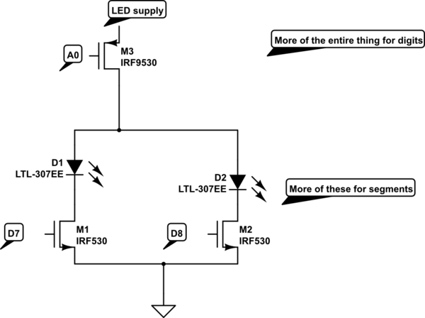
schematic

simulate this circuit – Schematic created using CircuitLab

This is a total of 6+7 == 13 digital outs. If you want to keep digital 0 and 1 for serial programming of the Arduino, use the Analog pins as outputs (it works fine!)

The program does this, over and over:

  • Set all digit driver pins to 0
  • Set all segment driver pins to 0
  • Turn on the next digit driver pin (A0..A5)
  • Turn on the appropriate set of segment driver pins (say, D7 .. D13)
  • Delay 4 milliseconds
  • go back

To update the "appropriate segments" for each digit, use a simple serial read poll. Drive the Arduino from the RPi, or a temporarily borrowed laptop.

No shift register needed! (If you have one, fine, you can run the diodes on 100% duty cycle instead of 1/6 duty cycle.)

Btw: The schematic editor built in here uses annoying MOSFET symbols with the arrow pointing differently from the most common symbol that uses three lines into the body. The bottom ones are N-channel; the top ones are P-channel.

After reading the updated question:

The main question is how you control the score in the first place. Maybe you can use a remote "ssh" connection into the Raspberry Pi to set the score, and have it output the score to the Arduino each time it updates. This means you need to write a little program on the RPi side to keep the serial port open and write news scores out. (Each time you open the serial port, the Arduino will reset!)

You need to run either wired Ethernet, or a wireless USB connector, to the RPi to be able to control it from a laptop/computer off-stage. If you don't yet know how to connect to a RPi or other Linux box using sshd (running Putty on the Windows side, or ssh from the Terminal on a Mac) now's the time to learn!

If you don't know how to write a program that opens a serial port and writes scores to it, now's the time to learn as well! (You can easily do this in Python.) There is a little bit of care needed to make sure that the right digit gets updated for each byte you receive from the RPi serial port; a simple protocol where you receive lines like:

XXX:YYY<CR>

would be all you need. Keep reading into a buffer on the Arduino side, and each time you get a , parse the line to set the scores.

I find that a convenient way of getting a lot of LEDs for a little money is flexible LED strips. You can put soft diffusing plastic on top of the strips to make the light more even.

You only need the Arduino for driving the score display. Build the LEDs into common-anode assemblies, one per digit, and switch the anode with a P-channel MOSFET and the cathodes with N-channel MOSFETs. You need six P-channel MOSFETs for the top end of each digit, and seven N-channel MOSFETs for the bottom end of each segment (you can tie the cathode of each segment of the same kind together, as you won't be driving more than one at a time.)

To drive the P-channel FETs, you need a small-signal N-channel FET as a pull-down, and a kilo-ohm-size resistor for a pull-up for the P-channel FET.

schematic

simulate this circuit – Schematic created using CircuitLab

This is a total of 6+7 == 13 digital outs. If you want to keep digital 0 and 1 for serial programming of the Arduino, use the Analog pins as outputs (it works fine!)

The program does this, over and over:

  • Set all digit driver pins to 0
  • Set all segment driver pins to 0
  • Turn on the next digit driver pin (A0..A5)
  • Turn on the appropriate set of segment driver pins (say, D7 .. D13)
  • Delay 4 milliseconds
  • go back

To update the "appropriate segments" for each digit, use a simple serial read poll. Drive the Arduino from the RPi, or a temporarily borrowed laptop.

No shift register needed! (If you have one, fine, you can run the diodes on 100% duty cycle instead of 1/6 duty cycle.)

Btw: The schematic editor built in here uses annoying MOSFET symbols with the arrow pointing differently from the most common symbol that uses three lines into the body. The bottom ones are N-channel; the top ones are P-channel.

The main question is how you control the score in the first place. Maybe you can use a remote "ssh" connection into the Raspberry Pi to set the score, and have it output the score to the Arduino each time it updates. This means you need to write a little program on the RPi side to keep the serial port open and write news scores out. (Each time you open the serial port, the Arduino will reset!)

I find that a convenient way of getting a lot of LEDs for a little money is flexible LED strips. You can put soft diffusing plastic on top of the strips to make the light more even.

You only need the Arduino for driving the score display. Build the LEDs into common-anode assemblies, one per digit, and switch the anode with a P-channel MOSFET and the cathodes with N-channel MOSFETs. You need six P-channel MOSFETs for the top end of each digit, and seven N-channel MOSFETs for the bottom end of each segment (you can tie the cathode of each segment of the same kind together, as you won't be driving more than one at a time.)

To drive the P-channel FETs, you need a small-signal N-channel FET as a pull-down, and a kilo-ohm-size resistor for a pull-up for the P-channel FET.

schematic

simulate this circuit – Schematic created using CircuitLab

This is a total of 6+7 == 13 digital outs. If you want to keep digital 0 and 1 for serial programming of the Arduino, use the Analog pins as outputs (it works fine!)

The program does this, over and over:

  • Set all digit driver pins to 0
  • Set all segment driver pins to 0
  • Turn on the next digit driver pin (A0..A5)
  • Turn on the appropriate set of segment driver pins (say, D7 .. D13)
  • Delay 4 milliseconds
  • go back

To update the "appropriate segments" for each digit, use a simple serial read poll. Drive the Arduino from the RPi, or a temporarily borrowed laptop.

No shift register needed! (If you have one, fine, you can run the diodes on 100% duty cycle instead of 1/6 duty cycle.)

Btw: The schematic editor built in here uses annoying MOSFET symbols with the arrow pointing differently from the most common symbol that uses three lines into the body. The bottom ones are N-channel; the top ones are P-channel.

After reading the updated question:

The main question is how you control the score in the first place. Maybe you can use a remote "ssh" connection into the Raspberry Pi to set the score, and have it output the score to the Arduino each time it updates. This means you need to write a little program on the RPi side to keep the serial port open and write news scores out. (Each time you open the serial port, the Arduino will reset!)

You need to run either wired Ethernet, or a wireless USB connector, to the RPi to be able to control it from a laptop/computer off-stage. If you don't yet know how to connect to a RPi or other Linux box using sshd (running Putty on the Windows side, or ssh from the Terminal on a Mac) now's the time to learn!

If you don't know how to write a program that opens a serial port and writes scores to it, now's the time to learn as well! (You can easily do this in Python.) There is a little bit of care needed to make sure that the right digit gets updated for each byte you receive from the RPi serial port; a simple protocol where you receive lines like:

XXX:YYY<CR>

would be all you need. Keep reading into a buffer on the Arduino side, and each time you get a , parse the line to set the scores.

Source Link
Jon Watte
  • 5.8k
  • 27
  • 37

I find that a convenient way of getting a lot of LEDs for a little money is flexible LED strips. You can put soft diffusing plastic on top of the strips to make the light more even.

You only need the Arduino for driving the score display. Build the LEDs into common-anode assemblies, one per digit, and switch the anode with a P-channel MOSFET and the cathodes with N-channel MOSFETs. You need six P-channel MOSFETs for the top end of each digit, and seven N-channel MOSFETs for the bottom end of each segment (you can tie the cathode of each segment of the same kind together, as you won't be driving more than one at a time.)

To drive the P-channel FETs, you need a small-signal N-channel FET as a pull-down, and a kilo-ohm-size resistor for a pull-up for the P-channel FET.

schematic

simulate this circuit – Schematic created using CircuitLab

This is a total of 6+7 == 13 digital outs. If you want to keep digital 0 and 1 for serial programming of the Arduino, use the Analog pins as outputs (it works fine!)

The program does this, over and over:

  • Set all digit driver pins to 0
  • Set all segment driver pins to 0
  • Turn on the next digit driver pin (A0..A5)
  • Turn on the appropriate set of segment driver pins (say, D7 .. D13)
  • Delay 4 milliseconds
  • go back

To update the "appropriate segments" for each digit, use a simple serial read poll. Drive the Arduino from the RPi, or a temporarily borrowed laptop.

No shift register needed! (If you have one, fine, you can run the diodes on 100% duty cycle instead of 1/6 duty cycle.)

Btw: The schematic editor built in here uses annoying MOSFET symbols with the arrow pointing differently from the most common symbol that uses three lines into the body. The bottom ones are N-channel; the top ones are P-channel.

The main question is how you control the score in the first place. Maybe you can use a remote "ssh" connection into the Raspberry Pi to set the score, and have it output the score to the Arduino each time it updates. This means you need to write a little program on the RPi side to keep the serial port open and write news scores out. (Each time you open the serial port, the Arduino will reset!)