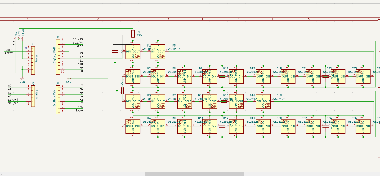
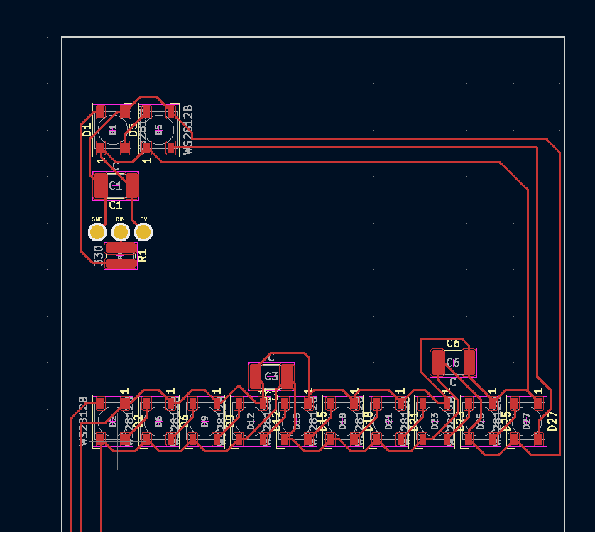
I am currently working on an LED clock project, and one of the things I would like to use is the SMDs found in WS2812B neopixel. I could simply use the LED strip itself, but I wanted to use a custom setup for the SMDs, so I thought about designing the PCB. However, I don't have a lot of experience designing PCBs, so I'm not really sure if I'm doing things correctly.
So I wanted the LED to be arranged in a zig-zag way that starts from the top left. I included the resistor (330 ohmsΩ) at the beginning and I connected a capacitor (supposedly somewhere between 100uF100 to 1000uF1000 uF) to one of the SMDs for every 4 SMDs (I asked for suggestion from someone who knows PCB way better than I do, and he suggested that it's probably fine to have 1 for every 4 SMDs).
I would have bought a sample or 1 one of this board to test out and fix whatever I did wrong, but I am currently short on time, so I'm hoping I could get some help in getting feedback on what I did wrong before ordering the PCB.


