I am searching for the right MOSFET that:

  • Can control a high power LED strip of either 12 V or 24 V.

  • Must be a through hole component (because I intend to solder everything by hand).

  • Should be controllable off of 3.3 V GPIO (I'll use a Wemos D1 mini, and not an Arduino).

I found out a few candidates on this forum already, but I am afraid of running them with 3.3 V only on the gate:

  • IRL540IRL540 with an RDS(on) of 0.11 Ω with Vgs = 4 V (which means I'll get even more resistance out of 3.3 V)

  • RFP30N06LE designed for slightly lower Vdss (but largely fills my 24 V requirements). There is no Rds(on) specified with a Vgs lower than 5 V.

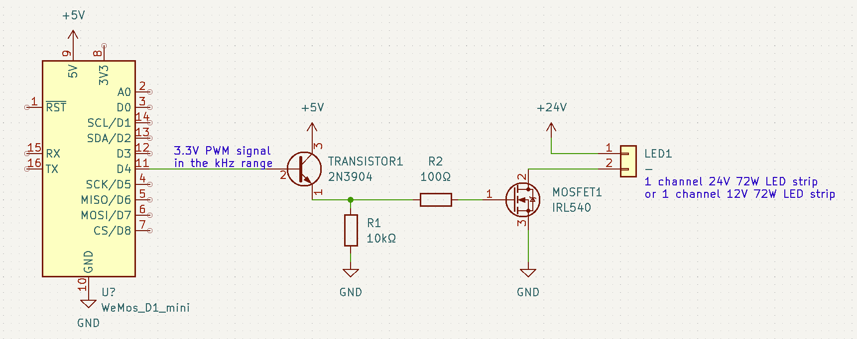
Considering one channel only for now, I came up with the following diagram:

enter image description here

  • How do I compute R2's value to avoid ringing and should I place it before or after the pull-down resistor? The discussion on Sizing MOSFET gate resistor was not really clear on the subject about it forming a voltage divider.

  • Is the transistor pertinent to drive the MOSFET with 5 V in order to have a lower Rds(on) resistance, or can I get away controlling the MOSFET directly from 3.3 V?

  • Is there anything I missed or that I forgot to take into account? I am fairly new to electrical engineering so there are a lot of concepts that I am not aware of. I always try to document myself before posting a question, but we never know.

I am searching for the right MOSFET that:

  • Can control a high power LED strip of either 12 V or 24 V.

  • Must be a through hole component (because I intend to solder everything by hand).

  • Should be controllable off of 3.3 V GPIO (I'll use a Wemos D1 mini, and not an Arduino).

I found out a few candidates on this forum already, but I am afraid of running them with 3.3 V only on the gate:

  • IRL540 with an RDS(on) of 0.11 Ω with Vgs = 4 V (which means I'll get even more resistance out of 3.3 V)

  • RFP30N06LE designed for slightly lower Vdss (but largely fills my 24 V requirements). There is no Rds(on) specified with a Vgs lower than 5 V.

Considering one channel only for now, I came up with the following diagram:

enter image description here

  • How do I compute R2's value to avoid ringing and should I place it before or after the pull-down resistor? The discussion on Sizing MOSFET gate resistor was not really clear on the subject about it forming a voltage divider.

  • Is the transistor pertinent to drive the MOSFET with 5 V in order to have a lower Rds(on) resistance, or can I get away controlling the MOSFET directly from 3.3 V?

  • Is there anything I missed or that I forgot to take into account? I am fairly new to electrical engineering so there are a lot of concepts that I am not aware of. I always try to document myself before posting a question, but we never know.

added 1 character in body; edited title
Source Link
winny
  • 16.8k
  • 6
  • 50
  • 71

Drive 24 V LED strip using 3.3 V Wemos D1 mini and mosfetsMOSFETs

I am searching for the right MOSFET that:

  • Can control a high power LED strip of either 12 V or 24 V.

  • Must be a through hole component (because I intend to solder everything by hand).

  • Should be controllable off of 3.3 V GPIO (I'll use a Wemos D1 mini, and not an Arduino).

I found out a few candidates on this forum already, but I am afraid of running them with 3.3 V only on the gate:

  • IRL540 with an RDS(on) of 0.11Ω11 Ω with Vgs = 4 V (which means I'll get even more resistance out of 3.3 V)

  • RFP30N06LE designed for slightly lower Vdss (but largely fills my 24 V requirements). There is no Rds(on) specified with a Vgs lower than 5 V.

Considering one channel only for now, I came up with the following diagram:

enter image description here

  • How do I compute R2's value to avoid ringing and should I place it before or after the pull-down resistor? The discussion on Sizing MOSFET gate resistor was not really clear on the subject about it forming a voltage divider.

  • Is the transistor pertinent to drive the MOSFET with 5 V in order to have a lower Rds(on) resistance, or can I get away controlling the MOSFET directly from 3.3 V?

  • Is there anything I missed or that I forgot to take into account? I am fairly new to electrical engineering so there are a lot of concepts that I am not aware of. I always try to document myself before posting a question, but we never know.

Drive 24 V LED strip using 3.3 V Wemos D1 mini and mosfets

I am searching for the right MOSFET that:

  • Can control a high power LED strip of either 12 V or 24 V.

  • Must be a through hole component (because I intend to solder everything by hand).

  • Should be controllable off of 3.3 V GPIO (I'll use a Wemos D1 mini, and not an Arduino).

I found out a few candidates on this forum already, but I am afraid of running them with 3.3 V only on the gate:

  • IRL540 with an RDS(on) of 0.11Ω with Vgs = 4 V (which means I'll get even more resistance out of 3.3 V)

  • RFP30N06LE designed for slightly lower Vdss (but largely fills my 24 V requirements). There is no Rds(on) specified with a Vgs lower than 5 V.

Considering one channel only for now, I came up with the following diagram:

enter image description here

  • How do I compute R2's value to avoid ringing and should I place it before or after the pull-down resistor? The discussion on Sizing MOSFET gate resistor was not really clear on the subject about it forming a voltage divider.

  • Is the transistor pertinent to drive the MOSFET with 5 V in order to have a lower Rds(on) resistance, or can I get away controlling the MOSFET directly from 3.3 V?

  • Is there anything I missed or that I forgot to take into account? I am fairly new to electrical engineering so there are a lot of concepts that I am not aware of. I always try to document myself before posting a question, but we never know.

Drive 24 V LED strip using 3.3 V Wemos D1 mini and MOSFETs

I am searching for the right MOSFET that:

  • Can control a high power LED strip of either 12 V or 24 V.

  • Must be a through hole component (because I intend to solder everything by hand).

  • Should be controllable off of 3.3 V GPIO (I'll use a Wemos D1 mini, and not an Arduino).

I found out a few candidates on this forum already, but I am afraid of running them with 3.3 V only on the gate:

  • IRL540 with an RDS(on) of 0.11 Ω with Vgs = 4 V (which means I'll get even more resistance out of 3.3 V)

  • RFP30N06LE designed for slightly lower Vdss (but largely fills my 24 V requirements). There is no Rds(on) specified with a Vgs lower than 5 V.

Considering one channel only for now, I came up with the following diagram:

enter image description here

  • How do I compute R2's value to avoid ringing and should I place it before or after the pull-down resistor? The discussion on Sizing MOSFET gate resistor was not really clear on the subject about it forming a voltage divider.

  • Is the transistor pertinent to drive the MOSFET with 5 V in order to have a lower Rds(on) resistance, or can I get away controlling the MOSFET directly from 3.3 V?

  • Is there anything I missed or that I forgot to take into account? I am fairly new to electrical engineering so there are a lot of concepts that I am not aware of. I always try to document myself before posting a question, but we never know.

remove space in IRL540 link
Source Link

I am searching for the right MOSFET that:

  • Can control a high power LED strip of either 12 V or 24 V.

  • Must be a through hole component (because I intend to solder everything by hand).

  • Should be controllable off of 3.3 V GPIO (I'll use a Wemos D1 mini, and not an Arduino).

I found out a few candidates on this forum already, but I am afraid of running them with 3.3 V only on the gate:

  • IRL540IRL540 with an RDS(on) of 0.11Ω with Vgs = 4 V (which means I'll get even more resistance out of 3.3 V)

  • RFP30N06LE designed for slightly lower Vdss (but largely fills my 24 V requirements). There is no Rds(on) specified with a Vgs lower than 5 V.

Considering one channel only for now, I came up with the following diagram:

enter image description here

  • How do I compute R2's value to avoid ringing and should I place it before or after the pull-down resistor? The discussion on Sizing MOSFET gate resistor was not really clear on the subject about it forming a voltage divider.

  • Is the transistor pertinent to drive the MOSFET with 5 V in order to have a lower Rds(on) resistance, or can I get away controlling the MOSFET directly from 3.3 V?

  • Is there anything I missed or that I forgot to take into account? I am fairly new to electrical engineering so there are a lot of concepts that I am not aware of. I always try to document myself before posting a question, but we never know.

I am searching for the right MOSFET that:

  • Can control a high power LED strip of either 12 V or 24 V.

  • Must be a through hole component (because I intend to solder everything by hand).

  • Should be controllable off of 3.3 V GPIO (I'll use a Wemos D1 mini, and not an Arduino).

I found out a few candidates on this forum already, but I am afraid of running them with 3.3 V only on the gate:

  • IRL540 with an RDS(on) of 0.11Ω with Vgs = 4 V (which means I'll get even more resistance out of 3.3 V)

  • RFP30N06LE designed for slightly lower Vdss (but largely fills my 24 V requirements). There is no Rds(on) specified with a Vgs lower than 5 V.

Considering one channel only for now, I came up with the following diagram:

enter image description here

  • How do I compute R2's value to avoid ringing and should I place it before or after the pull-down resistor? The discussion on Sizing MOSFET gate resistor was not really clear on the subject about it forming a voltage divider.

  • Is the transistor pertinent to drive the MOSFET with 5 V in order to have a lower Rds(on) resistance, or can I get away controlling the MOSFET directly from 3.3 V?

  • Is there anything I missed or that I forgot to take into account? I am fairly new to electrical engineering so there are a lot of concepts that I am not aware of. I always try to document myself before posting a question, but we never know.

Formatting/capitalization
Source Link
JYelton
  • 34.9k
  • 34
  • 147
  • 272
Loading
changed the link to a related question
Source Link
Loading
Source Link
Loading