Became Hot Network Question
added 4 characters in body
Source Link
Mhan
  • 730
  • 1
  • 11

I would be very happy if anyone can help me find answer regarding to questions below:

The lead compensator is added to the system to increase the phase margin.

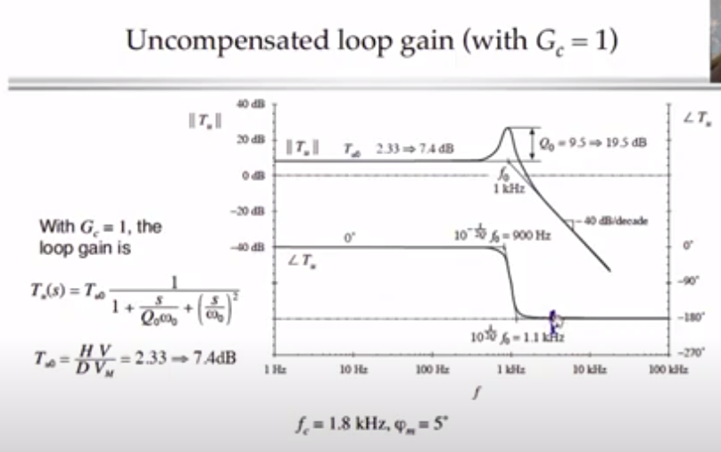
1'st picture is related to the uncompensated loop gain-phase graph.
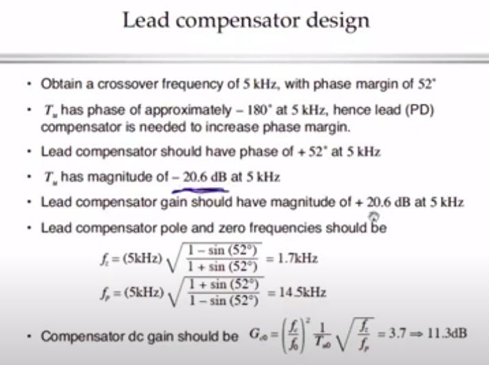
2'nd picture is the summary of the lead compensator. Poles and zeros are calculated to be added to our uncompensated transfer function.
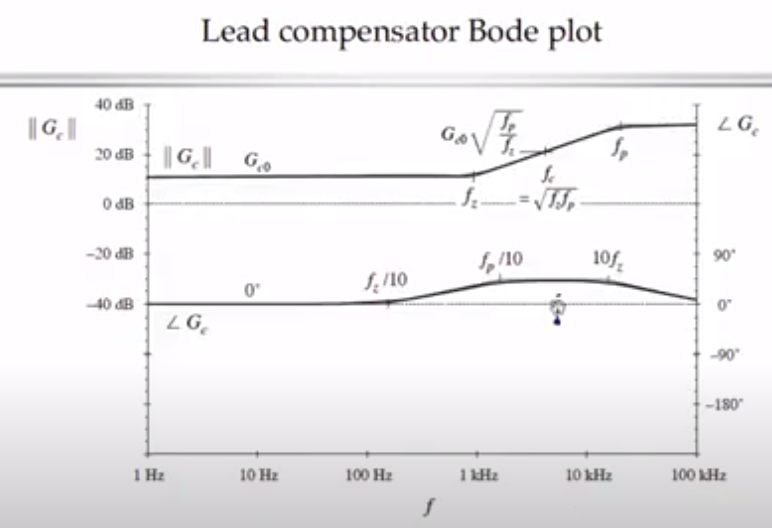
3'rd picture is the bode plot of lead compensator calculated to be added to the system.

My question is how did they calculate the compensator dc gain stated at the bottom of the 2'nd picture as Gc0= (fc/fo)*2x(1/Tco)x sqrt(fz/fp). I could not undestand that.

enter image description here

Source : Indus Electric Offical - Power Electronic 3 4 6 Design Example - https://www.youtube.com/watch?v=ABY43mX7UQo

enter image description here

Source : Indus Electric Offical - Power Electronic 3 4 6 Design Example - https://www.youtube.com/watch?v=ABY43mX7UQo
enter image description here

Source : Indus Electric Offical - Power Electronic 3 4 6 Design Example - https://www.youtube.com/watch?v=ABY43mX7UQo
I would be very happy if anyone can help me find answer regarding to questions below:

The lead compensator is added to the system to increase the phase margin.

1'st picture is related to the uncompensated loop gain-phase graph.
2'nd picture is the summary of the lead compensator. Poles and zeros are calculated to be added to our uncompensated transfer function.
3'rd picture is the bode plot of lead compensator calculated to be added to the system.

My question is how did they calculate the compensator dc gain stated at the bottom of the 2'nd picture as Gc0= (fc/fo)*2x(1/Tco)x sqrt(fz/fp). I could undestand that.

enter image description here

Source : Indus Electric Offical - Power Electronic 3 4 6 Design Example - https://www.youtube.com/watch?v=ABY43mX7UQo

enter image description here

Source : Indus Electric Offical - Power Electronic 3 4 6 Design Example - https://www.youtube.com/watch?v=ABY43mX7UQo

enter image description here

Source : Indus Electric Offical - Power Electronic 3 4 6 Design Example - https://www.youtube.com/watch?v=ABY43mX7UQo

I would be very happy if anyone can help me find answer regarding to questions below:

The lead compensator is added to the system to increase the phase margin.

1'st picture is related to the uncompensated loop gain-phase graph.
2'nd picture is the summary of the lead compensator. Poles and zeros are calculated to be added to our uncompensated transfer function.
3'rd picture is the bode plot of lead compensator calculated to be added to the system.

My question is how did they calculate the compensator dc gain stated at the bottom of the 2'nd picture as Gc0= (fc/fo)*2x(1/Tco)x sqrt(fz/fp). I could not undestand that.

enter image description here

Source : Indus Electric Offical - Power Electronic 3 4 6 Design Example - https://www.youtube.com/watch?v=ABY43mX7UQo

enter image description here

Source : Indus Electric Offical - Power Electronic 3 4 6 Design Example - https://www.youtube.com/watch?v=ABY43mX7UQo

enter image description here

Source : Indus Electric Offical - Power Electronic 3 4 6 Design Example - https://www.youtube.com/watch?v=ABY43mX7UQo

Source Link
Mhan
  • 730
  • 1
  • 11

Op-amp - Lead compensator design

I would be very happy if anyone can help me find answer regarding to questions below:

The lead compensator is added to the system to increase the phase margin.

1'st picture is related to the uncompensated loop gain-phase graph.
2'nd picture is the summary of the lead compensator. Poles and zeros are calculated to be added to our uncompensated transfer function.
3'rd picture is the bode plot of lead compensator calculated to be added to the system.

My question is how did they calculate the compensator dc gain stated at the bottom of the 2'nd picture as Gc0= (fc/fo)*2x(1/Tco)x sqrt(fz/fp). I could undestand that.

enter image description here

Source : Indus Electric Offical - Power Electronic 3 4 6 Design Example - https://www.youtube.com/watch?v=ABY43mX7UQo

enter image description here

Source : Indus Electric Offical - Power Electronic 3 4 6 Design Example - https://www.youtube.com/watch?v=ABY43mX7UQo

enter image description here

Source : Indus Electric Offical - Power Electronic 3 4 6 Design Example - https://www.youtube.com/watch?v=ABY43mX7UQo