OriginalSecond addition
As the question evolves, so can the answer :-).
There is no doubt that simple bang/bang on/off control is undesirable and causes undesirable battery current and voltage variations. My comments about the controller being able to control voltage are true over a long time period relative to a PWM cycle but all sorts of interesting stuff may happen over a single cycle or a small number of cycles.
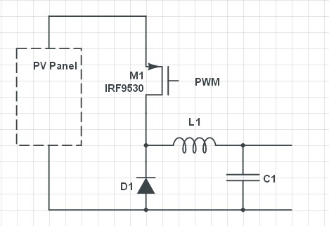
Adding an inductor allows energy storage and smoothing - an existing controller MAY be able to be "improved" by just adding an inductor and flyback diode and maybe one or 2 reservoir caps depending what is there now BUT the existing control circuitry may have a fit (or not) due to the changed response. It would probably in many cases to use the existing power level hardware with L,C,D as requisite plus either new software or (possibly more easily) a new control core. An MPPT controller needs cost little more than what is there now. Pricing is often controlled by "because we can" and "because they can't" factors.
Having the series switch (probably MOSFET) in linear or resistive more would help make behaviour nicer at the expense of power dissipation in the switch. The heatsink size is uncertain as can only be seen end on but it looks substantial. If the switch is run as a resistor then it COULD be setup to operate a setady current feed to battery. If desired this could be only done in holding mode where current is low. eg in Panle V_light)load is say 17V and Vbat hold is say 12.6V and Itrickle is say 100 mA then dissipation in a FET in this mode is P = V x I = (17 - 12.6) * 0.1 = 0.44 Watts = minimal. If you could sink say 5 Watts and needed to provide current from 18V to 12V you could have I = W/V = 5/(18-12) =~~ 800 mA.
Using on/off PWM is non ideal and will lead to waveforms something similar to those shown by Arik in his second edit. The magnitude of the spikes will depend on how much capacitance is present BEFORE the switch, to a lesser extent how much capacitance after the switch, wiring resistance (and to some extent inductance) and battery characteristics and state of charge and, importantly, PWM frequency. Arik has shown the signals as step changes at switching boundaries followed by linear ramps. I would expect the step changes to be modified by effect of capacitances and linear ramps to tail off into more or less steady state flat spots as PWM on or off time became long relative to battery & PV panel settling down to steady state under the given conditions.
I do not show a capacitor on the PV panel in my outline schematic below but if there is one then the PV panel will slew more slowly and can be held near a constant voltage more closely. This would limit the more objectionable spikes and excursions shown by Arik.
Also, an ideal battery may exhibit step change and "instantaneous steady state" conditions as suggested but it is likely that in real life you get more complex responses- an oscilloscope would be your friend here.
Original answer - useful but not what was asked for.


