In the Linear Technology AN 105 on current sensing one can find the following circuit.
I am wondering what the purpose of the 200 ohm resistor on the inverting input is. It appears to have no effect.
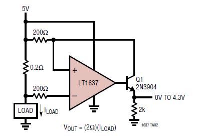
Note that in the following paragraph a virtually identical circuit is presented that is lacking said resistor:
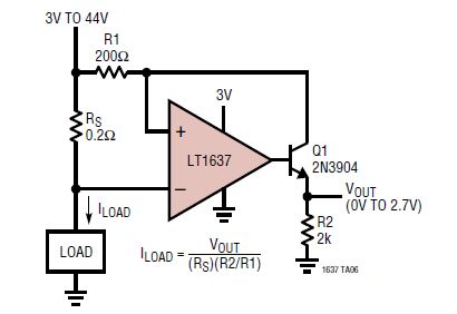
As a side issue: is there any downside to sizing the 200 ohm input impedance resistors significantly larger, e.g. 10k? (Keeping gain constant.) The aim would be to reduce the current the opamp draws from its supply to drive the BJT.
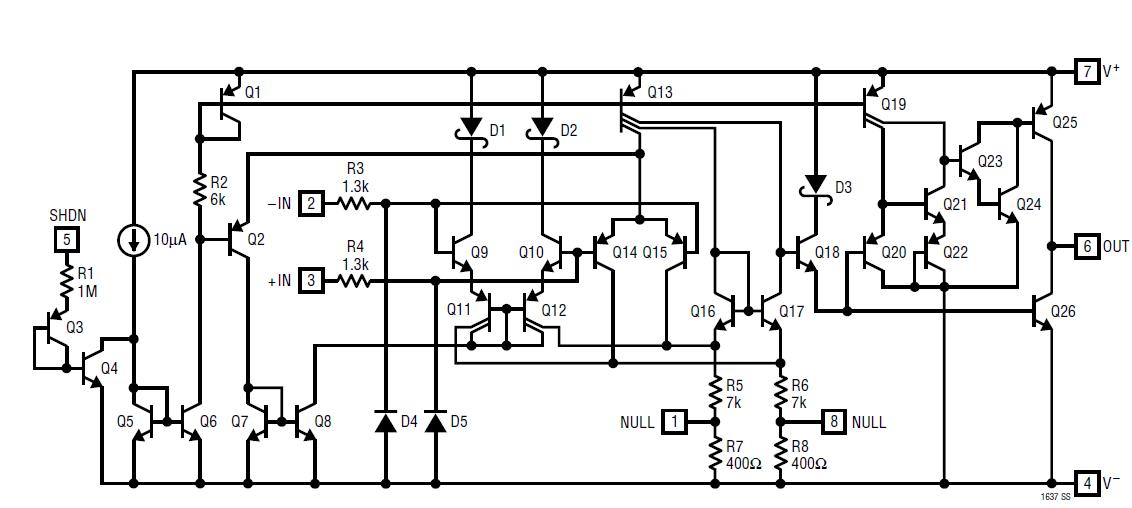
Edit 1: Need for Q1
In the comments it was questioned whether the output transistor Q1 was needed. See my comment below on my interpretation.
Edit 2: Johnson noise
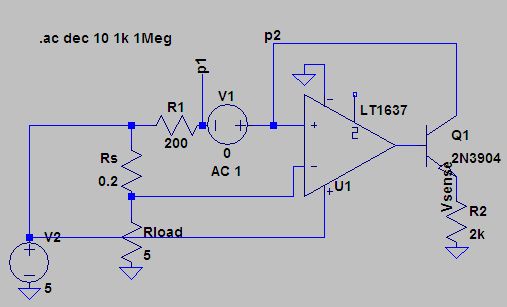
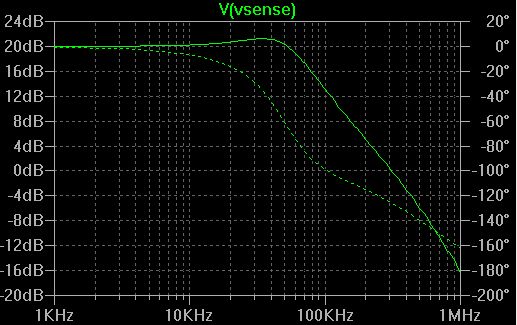
The Photon's back of the envelope calculation suggests that the input resistor's Johnson noise is not likely to be an issue even for large values if 0.1% (of output range) noise on the output is acceptable: $$ Vrms = 10\times \sqrt{R}\sqrt{\Delta f} \times 10^{-9}\text{in Volt}$$
For Vrms = 0.005V and 70kHz: $$ R = (\frac{Vrms}{1.3\times\sqrt{\Delta f}}\times 10^9 )^2 = 211 G\Omega $$
