added 28 characters in body
Source Link
Andy aka
  • 473k
  • 29
  • 383
  • 839

Two things: -

  • The 24V relay expects maybe 28Vmax and 24VAC will peak at possible 37V. Subtract a couple of volt drops for the diodes in the bridge and you are still at 35V so, I would put a 10V zener in series with the relay. Smoothing cap value needs to be 10uF plus but plan on it being as high as 100uF i.e. make room for a bigger component should it be needed. You might also have a catch diode across the relay coil to prevent back-emfs whn it switches off.
  • You'll need a pull-down resistor on the digital input so that when the contact is open circuit a definite state is forced onto the IO pin. (EDITED from pull-up)

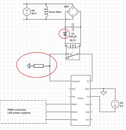
Here's the mods and where the zener is circled you'll need a regular diode across the relay, cathode to positive feed after the zener (BZX84C10V for the zener) and possibly a 1N400x for the diode : -
enter image description here

Good luck

Two things: -

  • The 24V relay expects maybe 28Vmax and 24VAC will peak at possible 37V. Subtract a couple of volt drops for the diodes in the bridge and you are still at 35V so, I would put a 10V zener in series with the relay. Smoothing cap value needs to be 10uF plus but plan on it being as high as 100uF i.e. make room for a bigger component should it be needed. You might also have a catch diode across the relay coil to prevent back-emfs whn it switches off.
  • You'll need a pull-down resistor on the digital input so that when the contact is open circuit a definite state is forced onto the IO pin. (EDITED from pull-up)

Here's the mods and where the zener is circled you'll need a regular diode across the relay, cathode to positive feed after the zener (BZX84C10V for the zener) and possibly a 1N400x for the diode : -

enter image description here

Good luck

added 28 characters in body
Source Link
Andy aka
  • 473k
  • 29
  • 383
  • 839

Two things: -

  • The 24V relay expects maybe 28Vmax and 24VAC will peak at possible 37V. Subtract a couple of volt drops for the diodes in the bridge and you are still at 35V so, I would put a 10V zener in series with the relay. Smoothing cap value needs to be 10uF plus but plan on it being as high as 100uF i.e. make room for a bigger component should it be needed. You might also have a catch diode across the relay coil to prevent back-emfs whn it switches off.
  • You'll need a pull-updown resistor on the digital input so that when the contact is open circuit a definite state is forced onto the IO pin. (EDITED from pull-up)

Good luck

Two things: -

  • The 24V relay expects maybe 28Vmax and 24VAC will peak at possible 37V. Subtract a couple of volt drops for the diodes in the bridge and you are still at 35V so, I would put a 10V zener in series with the relay. Smoothing cap value needs to be 10uF plus but plan on it being as high as 100uF i.e. make room for a bigger component should it be needed. You might also have a catch diode across the relay coil to prevent back-emfs whn it switches off.
  • You'll need a pull-up resistor on the digital input so that when the contact is open circuit a definite state is forced onto the IO pin.

Good luck

Two things: -

  • The 24V relay expects maybe 28Vmax and 24VAC will peak at possible 37V. Subtract a couple of volt drops for the diodes in the bridge and you are still at 35V so, I would put a 10V zener in series with the relay. Smoothing cap value needs to be 10uF plus but plan on it being as high as 100uF i.e. make room for a bigger component should it be needed. You might also have a catch diode across the relay coil to prevent back-emfs whn it switches off.
  • You'll need a pull-down resistor on the digital input so that when the contact is open circuit a definite state is forced onto the IO pin. (EDITED from pull-up)

Good luck

Source Link
Andy aka
  • 473k
  • 29
  • 383
  • 839

Two things: -

  • The 24V relay expects maybe 28Vmax and 24VAC will peak at possible 37V. Subtract a couple of volt drops for the diodes in the bridge and you are still at 35V so, I would put a 10V zener in series with the relay. Smoothing cap value needs to be 10uF plus but plan on it being as high as 100uF i.e. make room for a bigger component should it be needed. You might also have a catch diode across the relay coil to prevent back-emfs whn it switches off.
  • You'll need a pull-up resistor on the digital input so that when the contact is open circuit a definite state is forced onto the IO pin.

Good luck