added 180 characters in body
Source Link
Andy aka
  • 472.9k
  • 29
  • 382
  • 839

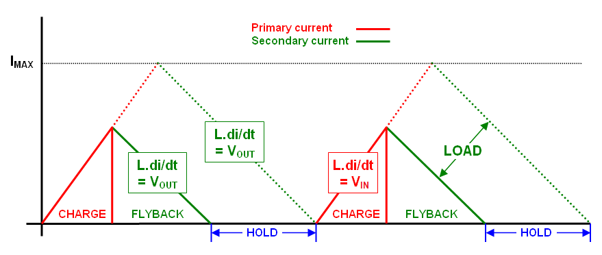
It's impossible to increase the CCM duty cycle on a fixed load without the output voltage changing. Consider the DCM flyback case: -

enter image description here

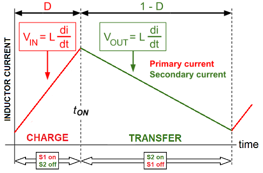
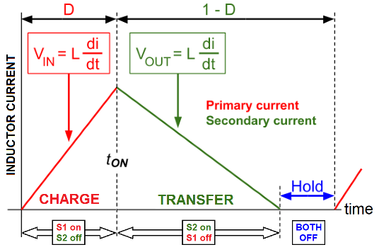
The slopes of the rise and fall of transformer current are wholly dictated by \$V_{IN}\$ and \$V_{OUT}\$ for an inductor of a fixed value. And, because there is a period at the end of the transfer phase in DCM, duty cycle variations are permissible: -

enter image description here

But, CCM has nowhere to accommodate a change in duty cycle: -

enter image description here

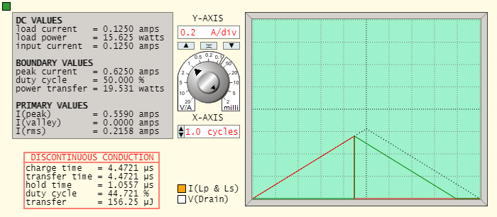
The images above come from my basic website and are for a flyback converter with a 1:1 transformer. I also have a waveform generator that you can use for testing the change from DCM into CCM as the load current increases. This is an example for a 1:1 transformer where the output voltage equals the input voltage (125 volts). DCM Operation is at 100 kHz with a 1000 Ω load: -

enter image description here

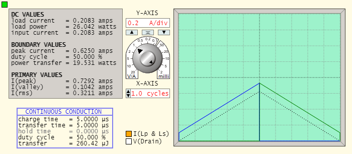
If I decrease the load to 800 Ω, operation is on the boundary between DCM/CCM: -

enter image description here

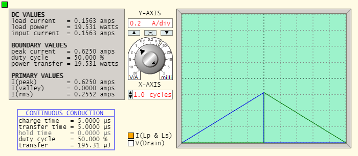
If I lower the load to 600 Ω, operation is clearly in CCM: -

enter image description here

The duty cycle cannot change because there is nowhere to accommodate that change hence, the whole primary and secondary waveform rises.

How do flyback converters operating in CCM regulate their output?

It naturally regulates in CCM due to the way the slopes of primary and secondary currents link together.

What is the controller doing to maintain the output voltage if the duty cycle is constant like that?

The controller doesn't need to do anything, it naturally happens once CCM is entered.

If the charging phase of the switching cycle begins when there is still magnetic energy in the transformer core (left over from the transfer phase) then, the charging current has to commence at a positive value and not a zero amp value (as in the case of DCM). That cannot be avoided in CCM.


Here'sSimple example of a flyback converter with fixed duty and switching frequency

The image shows a simple example of the flyback converter's current waveforms starting from the instant power up (but with a fixedis applied. Although the duty cycle) and switching frequency are fixed, CCM is naturally entered in the first few cycles but, after the output voltage rises towards a settled value, DCM takes over: -

enter image description here

Not until the output voltage rises to the appropriate level does the operation fall into DCM. In all cycles the red line (charging current) has the same length and duration. As you can see that converter naturally starts in CCM and naturally drops into DCM despite have a fixed and immutable duty cycle.

  • The red part of the waveform is charging current and,
  • The green part of the waveform is the transfer current to the load
  • Red remains fixed in duration and angle
  • Green starts shallow and gradually becomes steeper

It's impossible to increase the CCM duty cycle on a fixed load without the output voltage changing. Consider the DCM flyback case: -

enter image description here

The slopes of the rise and fall of transformer current are wholly dictated by \$V_{IN}\$ and \$V_{OUT}\$ for an inductor of a fixed value. And, because there is a period at the end of the transfer phase in DCM, duty cycle variations are permissible: -

enter image description here

But, CCM has nowhere to accommodate a change in duty cycle: -

enter image description here

The images above come from my basic website and are for a flyback converter with a 1:1 transformer. I also have a waveform generator that you can use for testing the change from DCM into CCM as the load current increases. This is an example for a 1:1 transformer where the output voltage equals the input voltage (125 volts). DCM Operation is at 100 kHz with a 1000 Ω load: -

enter image description here

If I decrease the load to 800 Ω, operation is on the boundary between DCM/CCM: -

enter image description here

If I lower the load to 600 Ω, operation is clearly in CCM: -

enter image description here

The duty cycle cannot change because there is nowhere to accommodate that change hence, the whole primary and secondary waveform rises.

How do flyback converters operating in CCM regulate their output?

It naturally regulates in CCM due to the way the slopes of primary and secondary currents link together.

What is the controller doing to maintain the output voltage if the duty cycle is constant like that?

The controller doesn't need to do anything, it naturally happens once CCM is entered.

If the charging phase of the switching cycle begins when there is still magnetic energy in the transformer core (left over from the transfer phase) then, the charging current has to commence at a positive value and not a zero amp value (as in the case of DCM). That cannot be avoided in CCM.

Here's a simple example of the flyback converter's current waveforms starting from power up (but with a fixed duty cycle): -

enter image description here

Not until the output voltage rises to the appropriate level does the operation fall into DCM. In all cycles the red line (charging current) has the same length and duration. As you can see that converter naturally starts in CCM and naturally drops into DCM despite have a fixed and immutable duty cycle.

It's impossible to increase the CCM duty cycle on a fixed load without the output voltage changing. Consider the DCM flyback case: -

enter image description here

The slopes of the rise and fall of transformer current are wholly dictated by \$V_{IN}\$ and \$V_{OUT}\$ for an inductor of a fixed value. And, because there is a period at the end of the transfer phase in DCM, duty cycle variations are permissible: -

enter image description here

But, CCM has nowhere to accommodate a change in duty cycle: -

enter image description here

The images above come from my basic website and are for a flyback converter with a 1:1 transformer. I also have a waveform generator that you can use for testing the change from DCM into CCM as the load current increases. This is an example for a 1:1 transformer where the output voltage equals the input voltage (125 volts). DCM Operation is at 100 kHz with a 1000 Ω load: -

enter image description here

If I decrease the load to 800 Ω, operation is on the boundary between DCM/CCM: -

enter image description here

If I lower the load to 600 Ω, operation is clearly in CCM: -

enter image description here

The duty cycle cannot change because there is nowhere to accommodate that change hence, the whole primary and secondary waveform rises.

How do flyback converters operating in CCM regulate their output?

It naturally regulates in CCM due to the way the slopes of primary and secondary currents link together.

What is the controller doing to maintain the output voltage if the duty cycle is constant like that?

The controller doesn't need to do anything, it naturally happens once CCM is entered.

If the charging phase of the switching cycle begins when there is still magnetic energy in the transformer core (left over from the transfer phase) then, the charging current has to commence at a positive value and not a zero amp value (as in the case of DCM). That cannot be avoided in CCM.


Simple example of a flyback converter with fixed duty and switching frequency

The image shows a flyback converter's current waveforms from the instant power is applied. Although the duty cycle and switching frequency are fixed, CCM is naturally entered in the first few cycles but, after the output voltage rises towards a settled value, DCM takes over: -

enter image description here

  • The red part of the waveform is charging current and,
  • The green part of the waveform is the transfer current to the load
  • Red remains fixed in duration and angle
  • Green starts shallow and gradually becomes steeper
added 183 characters in body
Source Link
Andy aka
  • 472.9k
  • 29
  • 382
  • 839

The short answer is thatIt's impossible to increase the CCM duty cycle cannot be increased because it's impossible to do soon a fixed load without the output voltage changing. Consider the DCM flyback case: -

enter image description here

The slopes of the rise and fall of transformer current are wholly dictated by \$V_{IN}\$ and \$V_{OUT}\$ for an inductor of a fixed value. ThisAnd, because there is also truea period at the end of the transfer phase in CCM butDCM, duty cycle variations are permissible: -

enter image description here

But, CCM has nowhere to accommodate a change in duty cycle: -

enter image description here

The images above come from my basic website and are for a flyback converter with a 1:1 transformer. I also have a waveform generator that you can use for testing the change from DCM into CCM as the load current increases. This is an example for a 1:1 transformer where the output voltage equals the input voltage (125 volts). DCM Operation is at 100 kHz with a 1000 Ω load: -

enter image description here

If I decrease the load to 800 Ω, operation is on the boundary between DCM/CCM: -

enter image description here

If I lower the load to 600 Ω, operation is clearly in CCM: -

enter image description here

The duty cycle cannot change because there is nowhere to accommodate that change hence, the whole primary and secondary waveform rises.

How do flyback converters operating in CCM regulate their output?

It naturally regulates in CCM due to the way the slopes of primary and secondary currents link together.

What is the controller doing to maintain the output voltage if the duty cycle is constant like that?

The controller doesn't need to do anything, it naturally happens once CCM is entered.

If the charging phase of the switching cycle begins when there is still magnetic energy in the transformer core (left over from the transfer phase) then, the charging current has to commence at a positive value and not a zero amp value (as in the case of DCM). That cannot be avoided in CCM.

Here's a simple example of the flyback converter's current waveforms starting from power up (but with a fixed duty cycle): -

enter image description here

Not until the output voltage rises to the appropriate level does the operation fall into DCM. In all cycles the red line (charging current) has the same length and duration. As you can see that converter naturally starts in CCM and naturally drops into DCM despite have a fixed and immutable duty cycle.

The short answer is that the duty cycle cannot be increased because it's impossible to do so. Consider the DCM flyback case: -

enter image description here

The slopes of the rise and fall of transformer current are wholly dictated by \$V_{IN}\$ and \$V_{OUT}\$ for an inductor of a fixed value. This is also true in CCM but, CCM has nowhere to accommodate a change in duty cycle: -

enter image description here

The images above come from my basic website and are for a flyback converter with a 1:1 transformer. I also have a waveform generator that you can use for testing the change from DCM into CCM as the load current increases. This is an example for a 1:1 transformer where the output voltage equals the input voltage (125 volts). DCM Operation is at 100 kHz with a 1000 Ω load: -

enter image description here

If I decrease the load to 800 Ω, operation is on the boundary between DCM/CCM: -

enter image description here

If I lower the load to 600 Ω, operation is clearly in CCM: -

enter image description here

The duty cycle cannot change because there is nowhere to accommodate that change hence, the whole primary and secondary waveform rises.

How do flyback converters operating in CCM regulate their output?

It naturally regulates in CCM due to the way the slopes of primary and secondary currents link together.

What is the controller doing to maintain the output voltage if the duty cycle is constant like that?

The controller doesn't need to do anything, it naturally happens once CCM is entered.

If the charging phase of the switching cycle begins when there is still magnetic energy in the transformer core (left over from the transfer phase) then, the charging current has to commence at a positive value and not a zero amp value (as in the case of DCM). That cannot be avoided in CCM.

Here's a simple example of the flyback converter's current waveforms starting from power up (but with a fixed duty cycle): -

enter image description here

Not until the output voltage rises to the appropriate level does the operation fall into DCM. In all cycles the red line (charging current) has the same length and duration. As you can see that converter naturally starts in CCM and naturally drops into DCM despite have a fixed and immutable duty cycle.

It's impossible to increase the CCM duty cycle on a fixed load without the output voltage changing. Consider the DCM flyback case: -

enter image description here

The slopes of the rise and fall of transformer current are wholly dictated by \$V_{IN}\$ and \$V_{OUT}\$ for an inductor of a fixed value. And, because there is a period at the end of the transfer phase in DCM, duty cycle variations are permissible: -

enter image description here

But, CCM has nowhere to accommodate a change in duty cycle: -

enter image description here

The images above come from my basic website and are for a flyback converter with a 1:1 transformer. I also have a waveform generator that you can use for testing the change from DCM into CCM as the load current increases. This is an example for a 1:1 transformer where the output voltage equals the input voltage (125 volts). DCM Operation is at 100 kHz with a 1000 Ω load: -

enter image description here

If I decrease the load to 800 Ω, operation is on the boundary between DCM/CCM: -

enter image description here

If I lower the load to 600 Ω, operation is clearly in CCM: -

enter image description here

The duty cycle cannot change because there is nowhere to accommodate that change hence, the whole primary and secondary waveform rises.

How do flyback converters operating in CCM regulate their output?

It naturally regulates in CCM due to the way the slopes of primary and secondary currents link together.

What is the controller doing to maintain the output voltage if the duty cycle is constant like that?

The controller doesn't need to do anything, it naturally happens once CCM is entered.

If the charging phase of the switching cycle begins when there is still magnetic energy in the transformer core (left over from the transfer phase) then, the charging current has to commence at a positive value and not a zero amp value (as in the case of DCM). That cannot be avoided in CCM.

Here's a simple example of the flyback converter's current waveforms starting from power up (but with a fixed duty cycle): -

enter image description here

Not until the output voltage rises to the appropriate level does the operation fall into DCM. In all cycles the red line (charging current) has the same length and duration. As you can see that converter naturally starts in CCM and naturally drops into DCM despite have a fixed and immutable duty cycle.

added 391 characters in body
Source Link
Andy aka
  • 472.9k
  • 29
  • 382
  • 839

The short answer is that the duty cycle cannot be increased because it's impossible to do so. Consider the DCM flyback case: -

enter image description here

The slopes of the rise and fall of transformer current are wholly dictated by \$V_{IN}\$ and \$V_{OUT}\$ for an inductor of a fixed value. This is also true in CCM but, CCM has nowhere to accommodate a change in duty cycle: -

enter image description here

The images above come from my basic website and are for a flyback converter with a 1:1 transformer. I also have a waveform generator that you can use for testing the change from DCM into CCM as the load current increases. This is an example for a 1:1 transformer where the output voltage equals the input voltage (125 volts). DCM Operation is at 100 kHz with a 1000 Ω load: -

enter image description here

If I decrease the load to 800 Ω, operation is on the boundary between DCM/CCM: -

enter image description here

If I lower the load to 600 Ω, operation is clearly in CCM: -

enter image description here

The duty cycle cannot change because there is nowhere to accommodate that change hence, the whole primary and secondary waveform rises.

How do flyback converters operating in CCM regulate their output?

It naturally regulates in CCM due to the way the slopes of primary and secondary currents link together.

What is the controller doing to maintain the output voltage if the duty cycle is constant like that?

The controller doesn't need to do anything, it naturally happens once CCM is entered.

If the charging phase of the switching cycle begins when there is still magnetic energy in the transformer core (left over from the transfer phase) then, the charging current has to commence at a positive value and not a zero amp value (as in the case of DCM). That cannot be avoided in CCM.

Here's a simple example of the flyback converter's current waveforms starting from power up (but with a fixed duty cycle): -

enter image description here

Not until the output voltage rises to the appropriate level does the operation fall into DCM. In all cycles the red line (charging current) has the same length and duration. As you can see that converter naturally starts in CCM and naturally drops into DCM despite have a fixed and immutable duty cycle.

The short answer is that the duty cycle cannot be increased because it's impossible to do so. Consider the DCM flyback case: -

enter image description here

The slopes of the rise and fall of transformer current are wholly dictated by \$V_{IN}\$ and \$V_{OUT}\$ for an inductor of a fixed value. This is also true in CCM but, CCM has nowhere to accommodate a change in duty cycle: -

enter image description here

The images above come from my basic website and are for a flyback converter with a 1:1 transformer. I also have a waveform generator that you can use for testing the change from DCM into CCM as the load current increases. This is an example for a 1:1 transformer where the output voltage equals the input voltage (125 volts). DCM Operation is at 100 kHz with a 1000 Ω load: -

enter image description here

If I decrease the load to 800 Ω, operation is on the boundary between DCM/CCM: -

enter image description here

If I lower the load to 600 Ω, operation is clearly in CCM: -

enter image description here

The duty cycle cannot change because there is nowhere to accommodate that change hence, the whole primary and secondary waveform rises.

How do flyback converters operating in CCM regulate their output?

It naturally regulates in CCM due to the way the slopes of primary and secondary currents link together.

What is the controller doing to maintain the output voltage if the duty cycle is constant like that?

The controller doesn't need to do anything, it naturally happens once CCM is entered.

If the charging phase of the switching cycle begins when there is still magnetic energy in the transformer core (left over from the transfer phase) then, the charging current has to commence at a positive value and not a zero amp value (as in the case of DCM). That cannot be avoided in CCM.

Here's a simple example of the flyback converter's current waveforms starting from power up (but with a fixed duty cycle): -

enter image description here

Not until the output voltage rises to the appropriate level does the operation fall into DCM. In all cycles the red line (charging current) has the same length and duration. As you can see that converter naturally starts in CCM and naturally drops into DCM despite have a fixed and immutable duty cycle.

added 260 characters in body
Source Link
Andy aka
  • 472.9k
  • 29
  • 382
  • 839
Loading
added 381 characters in body
Source Link
Andy aka
  • 472.9k
  • 29
  • 382
  • 839
Loading
added 833 characters in body
Source Link
Andy aka
  • 472.9k
  • 29
  • 382
  • 839
Loading
Source Link
Andy aka
  • 472.9k
  • 29
  • 382
  • 839
Loading