Became Hot Network Question
edited title
Link
JRE
  • 73.6k
  • 10
  • 112
  • 195

Yellow components on light intensity module PXBPCB

added 30 characters in body; edited title
Source Link
JRE
  • 73.6k
  • 10
  • 112
  • 195

Yellow components on light intensity module pcbPXB

Can anyone tell me what the yellow components on this pcbPCB are please? At

At first I thought diode - they measure 0.7 V but then 1.7V when measuring reverse-bias. Then

Then I thought capacitor - but the both measure 0 nF. What

What test should I do to find out what they are? They

They are part of a HALJIA Digital Light Intensity Sensor Modulelight intensity sensor module. The circuit is design to switch a DOdigital output when the light reaches a certain level that is adjustable using the potpotentiometer.

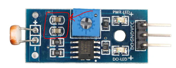
enter image description here

Yellow components on light intensity module pcb

Can anyone tell me what the yellow components on this pcb are please? At first I thought diode - they measure 0.7 V but then 1.7V when measuring reverse-bias. Then I thought capacitor - but the both measure 0 nF. What test should I do to find out what they are? They are part of a HALJIA Digital Light Intensity Sensor Module. The circuit is design to switch a DO when the light reaches a certain level that is adjustable using the pot.

enter image description here

Yellow components on light intensity module PXB

Can anyone tell me what the yellow components on this PCB are please?

At first I thought diode - they measure 0.7 V but then 1.7V when measuring reverse-bias.

Then I thought capacitor - but the both measure 0 nF.

What test should I do to find out what they are?

They are part of a HALJIA Digital light intensity sensor module. The circuit is design to switch a digital output when the light reaches a certain level that is adjustable using the potentiometer.

enter image description here

added 161 characters in body
Source Link

Can anyone tell me what the yellow components on this pcb are please? IAt first I thought diode - they measure 0.7 V but then 1.7V when measuring reverse-bias so not so sure. Then I thought capacitor - but the both measure 0 nF. What test should I do to find out what they are? They are part of a HALJIA Digital Light Intensity Sensor Module. The circuit is design to switch a DO when the light reaches a certain level that is adjustable using the pot.

enter image description here

Can anyone tell me what the yellow components on this pcb are please? I thought diode - they measure 0.7 V but then 1.7V when measuring reverse-bias so not so sure. What test should I do to find out what they are? They are part of a HALJIA Digital Light Intensity Sensor Module.

enter image description here

Can anyone tell me what the yellow components on this pcb are please? At first I thought diode - they measure 0.7 V but then 1.7V when measuring reverse-bias. Then I thought capacitor - but the both measure 0 nF. What test should I do to find out what they are? They are part of a HALJIA Digital Light Intensity Sensor Module. The circuit is design to switch a DO when the light reaches a certain level that is adjustable using the pot.

enter image description here

Source Link
Loading