Replaced resistors with current sources
Source Link
Simon Fitch
  • 47.4k
  • 3
  • 25
  • 135

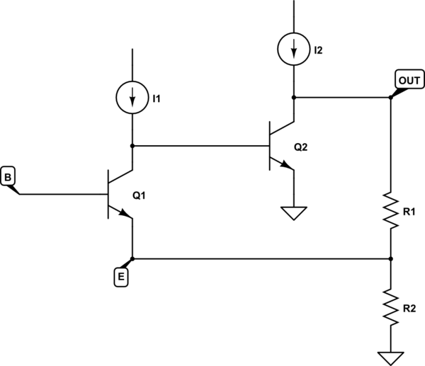
If you view the entire amplifier without any of the peripheral stuff that sets bias, or individual stage gains, and just assume that there are a couple of transistors whose combined gain is very large, it might look like this:

schematicschematic

simulate this circuitsimulate this circuit – Schematic created using CircuitLab

I've removed capacitors, assuming that they have zero impedance at frequencies of interest, and what's left is an amplifier whose input is really just the \$V_{BE}\$ of Q1, the potential difference between Q1's base and emitter.

This system is a simple non-inverting (two inverting stages cascaded) amplifier with quite a large open-loop gain. Assuming everything were biased in between saturation and cutoff, to permit voltage excursions up and down, we'd have this:

$$ \Delta V_{OUT} = A \Delta(V_B - V_E) $$

If potential \$V_E\$ were held constant, an increase in potential \$V_B\$ would create an increase in the potential difference \$V_{BE}\$, resulting in \$V_{OUT}\$ rising. An increase in \$V_E\$ while base \$V_B\$ is held fixed would have the opposite effect, reducing \$V_{BE}\$ and causing \$V_{OUT}\$ to fall instead.

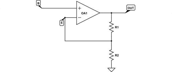
From this perspective, it's easy to see how B could be considered a non-inverting input, and E the inverting input, to an op-amp. Resistors R1 and R2 are feedback to the inverting input (thus feedback is negative), and the system looks like this:
schematic

simulate this circuit

This is clearly a non-inverting amplifier setup, with the familiar relationship:

$$ V_{OUT} = V_B \left( 1 + \frac{R_1}{R_2} \right) $$

I wouldn't expect this to be very precise here, because open-loop gain is not very large. It's probably a thousand or so, not the hundreds-of-thousands or millions you'd obtain from a real op-amp IC. Also, but it'sinput impedance is very low compared to an op-amp, which will influence the response slightly. It will be close enoughthough.

Here, R1 is the 4.7kΩ resistor feeding back from the output, and R2 is the 100Ω resistor to ground, so gain would be:

$$ \frac{V_{OUT}}{V_B} \approx \left(1 + \frac{R_1}{R_2}\right) \approx \left(1 + \frac{4700}{100}\right) \approx 50 $$

If you view the entire amplifier without any of the peripheral stuff that sets bias, or individual stage gains, and just assume that there are a couple of transistors whose combined gain is very large, it might look like this:

schematic

simulate this circuit – Schematic created using CircuitLab

I've removed capacitors, assuming that they have zero impedance at frequencies of interest, and what's left is an amplifier whose input is really just the \$V_{BE}\$ of Q1, the potential difference between Q1's base and emitter.

This system is a simple non-inverting (two inverting stages cascaded) amplifier with quite a large open-loop gain. Assuming everything were biased in between saturation and cutoff, to permit voltage excursions up and down, we'd have this:

$$ \Delta V_{OUT} = A \Delta(V_B - V_E) $$

If potential \$V_E\$ were held constant, an increase in potential \$V_B\$ would create an increase in the potential difference \$V_{BE}\$, resulting in \$V_{OUT}\$ rising. An increase in \$V_E\$ while base \$V_B\$ is held fixed would have the opposite effect, reducing \$V_{BE}\$ and causing \$V_{OUT}\$ to fall instead.

From this perspective, it's easy to see how B could be considered a non-inverting input, and E the inverting input, to an op-amp. Resistors R1 and R2 are feedback to the inverting input (thus feedback is negative), and the system looks like this:

schematic

simulate this circuit

This is clearly a non-inverting amplifier setup, with the familiar relationship:

$$ V_{OUT} = V_B \left( 1 + \frac{R_1}{R_2} \right) $$

I wouldn't expect this to be very precise here, because open-loop gain is not very large. It's probably a thousand or so, not the hundreds-of-thousands or millions you'd obtain from a real op-amp IC, but it's close enough.

Here, R1 is the 4.7kΩ resistor feeding back from the output, and R2 is the 100Ω resistor to ground, so gain would be:

$$ \frac{V_{OUT}}{V_B} \approx \left(1 + \frac{R_1}{R_2}\right) \approx \left(1 + \frac{4700}{100}\right) \approx 50 $$

If you view the entire amplifier without any of the peripheral stuff that sets bias, or individual stage gains, and just assume that there are a couple of transistors whose combined gain is very large, it might look like this:

schematic

simulate this circuit – Schematic created using CircuitLab

I've removed capacitors, assuming that they have zero impedance at frequencies of interest, and what's left is an amplifier whose input is really just the \$V_{BE}\$ of Q1, the potential difference between Q1's base and emitter.

This system is a simple non-inverting (two inverting stages cascaded) amplifier with quite a large open-loop gain. Assuming everything were biased in between saturation and cutoff, to permit voltage excursions up and down, we'd have this:

$$ \Delta V_{OUT} = A \Delta(V_B - V_E) $$

If potential \$V_E\$ were held constant, an increase in potential \$V_B\$ would create an increase in the potential difference \$V_{BE}\$, resulting in \$V_{OUT}\$ rising. An increase in \$V_E\$ while base \$V_B\$ is held fixed would have the opposite effect, reducing \$V_{BE}\$ and causing \$V_{OUT}\$ to fall instead.

From this perspective, it's easy to see how B could be considered a non-inverting input, and E the inverting input, to an op-amp. Resistors R1 and R2 are feedback to the inverting input (thus feedback is negative), and the system looks like this:

schematic

simulate this circuit

This is clearly a non-inverting amplifier setup, with the familiar relationship:

$$ V_{OUT} = V_B \left( 1 + \frac{R_1}{R_2} \right) $$

I wouldn't expect this to be very precise here, because open-loop gain is not very large. It's probably a thousand or so, not the hundreds-of-thousands or millions you'd obtain from a real op-amp IC. Also, input impedance is very low compared to an op-amp, which will influence the response slightly. It will be close though.

Here, R1 is the 4.7kΩ resistor feeding back from the output, and R2 is the 100Ω resistor to ground, so gain would be:

$$ \frac{V_{OUT}}{V_B} \approx \left(1 + \frac{R_1}{R_2}\right) \approx \left(1 + \frac{4700}{100}\right) \approx 50 $$

Source Link
Simon Fitch
  • 47.4k
  • 3
  • 25
  • 135

If you view the entire amplifier without any of the peripheral stuff that sets bias, or individual stage gains, and just assume that there are a couple of transistors whose combined gain is very large, it might look like this:

schematic

simulate this circuit – Schematic created using CircuitLab

I've removed capacitors, assuming that they have zero impedance at frequencies of interest, and what's left is an amplifier whose input is really just the \$V_{BE}\$ of Q1, the potential difference between Q1's base and emitter.

This system is a simple non-inverting (two inverting stages cascaded) amplifier with quite a large open-loop gain. Assuming everything were biased in between saturation and cutoff, to permit voltage excursions up and down, we'd have this:

$$ \Delta V_{OUT} = A \Delta(V_B - V_E) $$

If potential \$V_E\$ were held constant, an increase in potential \$V_B\$ would create an increase in the potential difference \$V_{BE}\$, resulting in \$V_{OUT}\$ rising. An increase in \$V_E\$ while base \$V_B\$ is held fixed would have the opposite effect, reducing \$V_{BE}\$ and causing \$V_{OUT}\$ to fall instead.

From this perspective, it's easy to see how B could be considered a non-inverting input, and E the inverting input, to an op-amp. Resistors R1 and R2 are feedback to the inverting input (thus feedback is negative), and the system looks like this:

schematic

simulate this circuit

This is clearly a non-inverting amplifier setup, with the familiar relationship:

$$ V_{OUT} = V_B \left( 1 + \frac{R_1}{R_2} \right) $$

I wouldn't expect this to be very precise here, because open-loop gain is not very large. It's probably a thousand or so, not the hundreds-of-thousands or millions you'd obtain from a real op-amp IC, but it's close enough.

Here, R1 is the 4.7kΩ resistor feeding back from the output, and R2 is the 100Ω resistor to ground, so gain would be:

$$ \frac{V_{OUT}}{V_B} \approx \left(1 + \frac{R_1}{R_2}\right) \approx \left(1 + \frac{4700}{100}\right) \approx 50 $$