If you want to compare SPICE engines one-to-one while avoiding any user error, you should first build it in LTspice and export the netlist (via menu command View->SPICE Netlist) to a text file. Then you can run that netlist text file in both LTspice directly and ngspice directly. You can add a .control section to the end of the netlist for ngspice if needed, but it's not necessary if you're OK with just typing run and plot V(Vosc) manually in ngspice. Adding an additional UI through Xschem just complicates things since you add the possibility that you drew/constructed the circuits differently through both UIs.
Here is my attempt at doing what I suggested above. Below is my exported netlist. I had to change the .tran command a bit since LTspice uses a unique syntax for .tran. You also had erroneous .ic commands I got rid of that LTspice was simply ignoring.
* InverterRingOsc.asc
XX1 Vosc N001 cmos_inverter
XX2 N001 N002 cmos_inverter
XX3 N002 Vosc cmos_inverter
C1 N001 0 0.2f
C2 N002 0 0.2f
C3 Vosc 0 0.2f

* block symbol definitions
.subckt cmos_inverter In Out
M1 Out In 0 N002 CMOSN l={L} w={WN} ad={AsN} as={AsN} pd={PsN} ps={PsN}
M2 Vdd In Out N001 CMOSP l={L} w={WP} ad={AsP} as={AsP} pd={PsP} ps={PsP}
Vdd1 Vdd 0 0.95
.param L=45n WN=135n WP=270n AsN=WN*L AsP=WP*L PsN=WN+2*L PsP=WP+2*L tola=0.05
.ends cmos_inverter

* .dc Vin 0 1.8 0.01
* .ac dec 100 50 10G
.ic V(Vosc)=0
.tran 0.1p 0.2n
.temp 75
.include 45nm_SS.pm
* .param tolb=0.03 tola=0.05
* .step param run 1 100 1
.end
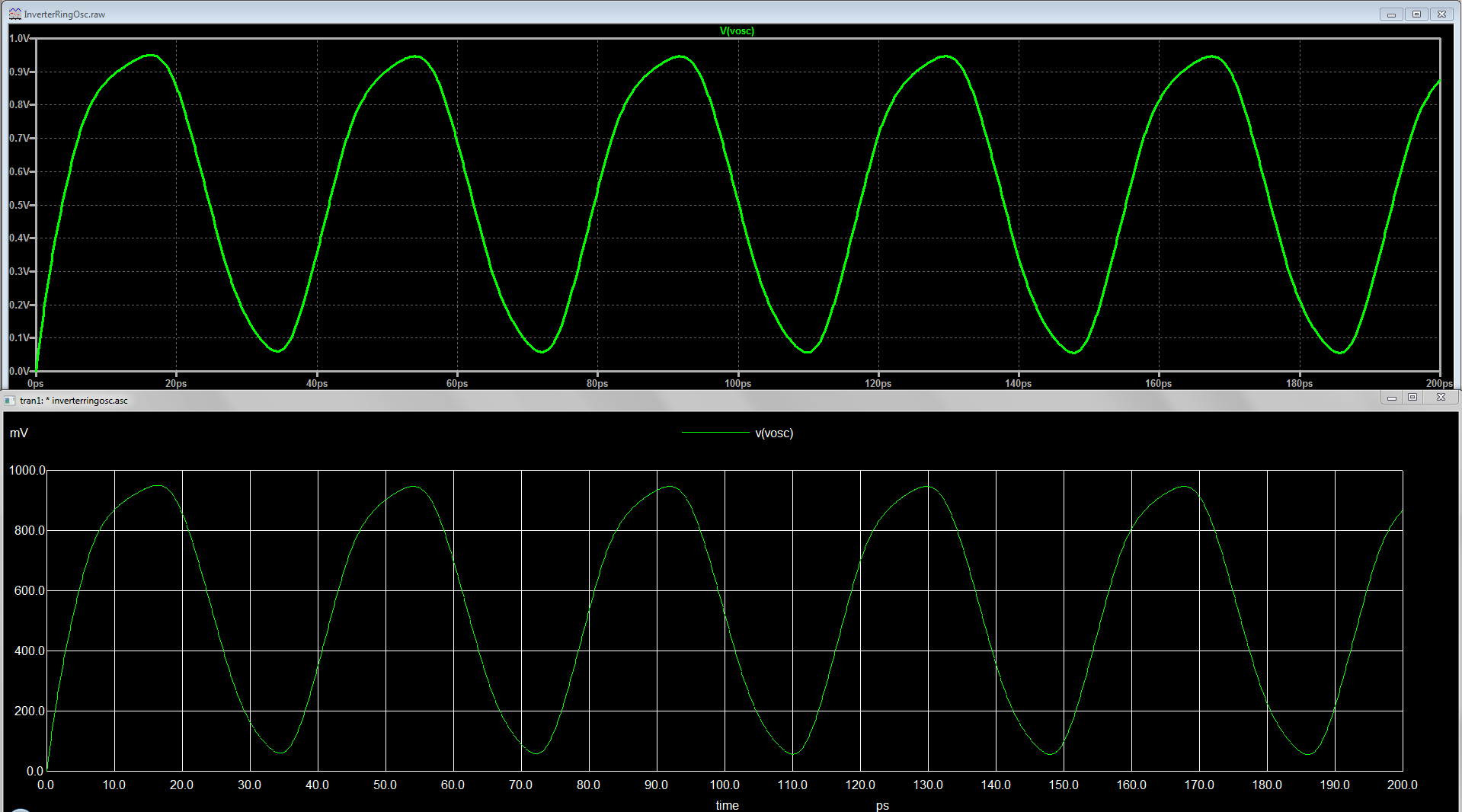
And here is the plot of V(Vosc) between both programs. They are identical.

This means there is a discrepancy in how you constructed the circuits in each UI.
I believe I found it here in the lines for the MOSFET instances:
LTspice:
M1 Out In 0 N002 CMOSN l={L} w={WN} ad={AsN} as={AsN} pd={PsN} ps={PsN}
M2 Vdd In Out N001 CMOSP l={L} w={WP} ad={AsP} as={AsP} pd={PsP} ps={PsP}
Xschem:
M1 net1 osc GND GND nmos w={WN} l={L} ad={AsN} as={AsN} pd={PsN} ps={PsN} m=1
M2 net1 osc VDD VDD pmos w={WP} l={L} ad={AsP} as={AsP} pd={PsP} ps={PsP} m=1
The body nodes in the LTspice version are floating! They should be connected to the source nodes, as you were intending. This happens because of how you used the nmos4 and pmos4 symbols when drawing the circuit in LTspice.
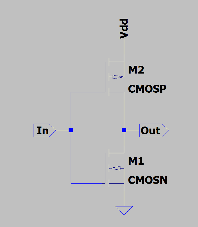
This is how you drew it:

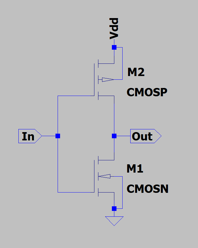
This is how you should draw it:

In your version, the wires hanging off the body pins are dangling and not connected to anything. It's a bit hard to see since the default color scheme uses light blue for wires and dark blue for symbol drawings. You're visually mistaking part of the symbol drawing for a wire. Some people change the default color scheme to prevent these kinds of things from happening. I can see the color difference, so it doesn't bother me.
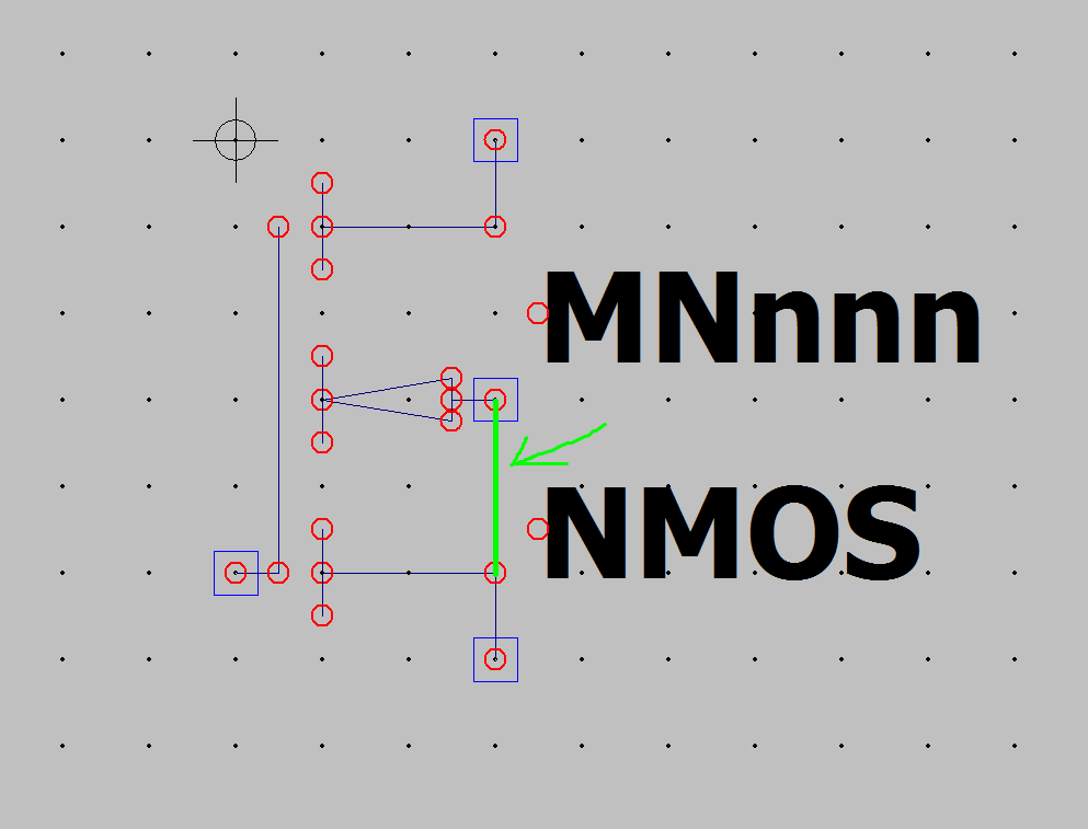
You can get a better idea of why this happens by editing the nmos4 symbol. Those circles surrounded by squares are the actual pins. You drew a wire from one pin to just a plain old line which does nothing.

TLDR:
You can trust both simulators, just be a little more mindful of your own proclivity for errors.