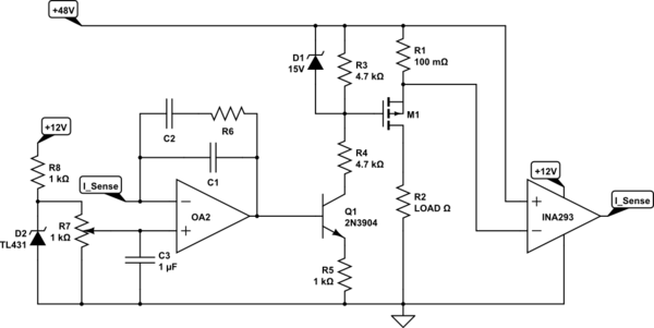
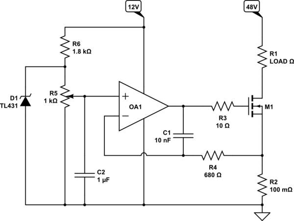
Your first circuit doesn't work the way you want because you lack a precision reference - Vbe is not a precision voltage reference. Your second circuit has the same problem as the first, but this time, the amplifier is unstable because you have no compensation for the capacitive load presented by the MOSFET gate. Here's how I would do the circuit that will do what you want:


simulate this circuitsimulate this circuit – Schematic created using CircuitLab
This is a High-current, constant-current source. But it will function as a current limiter.
There are simpler solutions available if you are doing low-side sensing. Even simpler if you're load was only a few hundred mA. The issue is detecting a lot of current while minimizing heat in the shunt resistor. INA293 and R1 could be replaced with a hall-effect current sensor. The exact details of the design will depend on your application requirements.
Edit: updated schematic per @TimWilliams observation.
Per comments, here's the simpler low-side version:

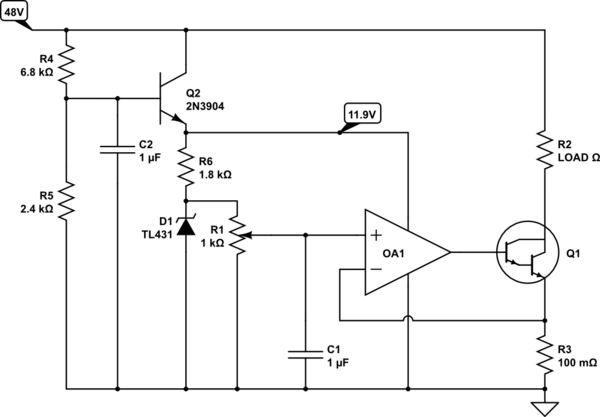
Or with the Darlington:

This one also has an added unregulated power supply to bring down the 48V. It could be used in all three circuits I posted. There's a lot of flexibility here so the parts aren't critical and performance can be easily tailored.
