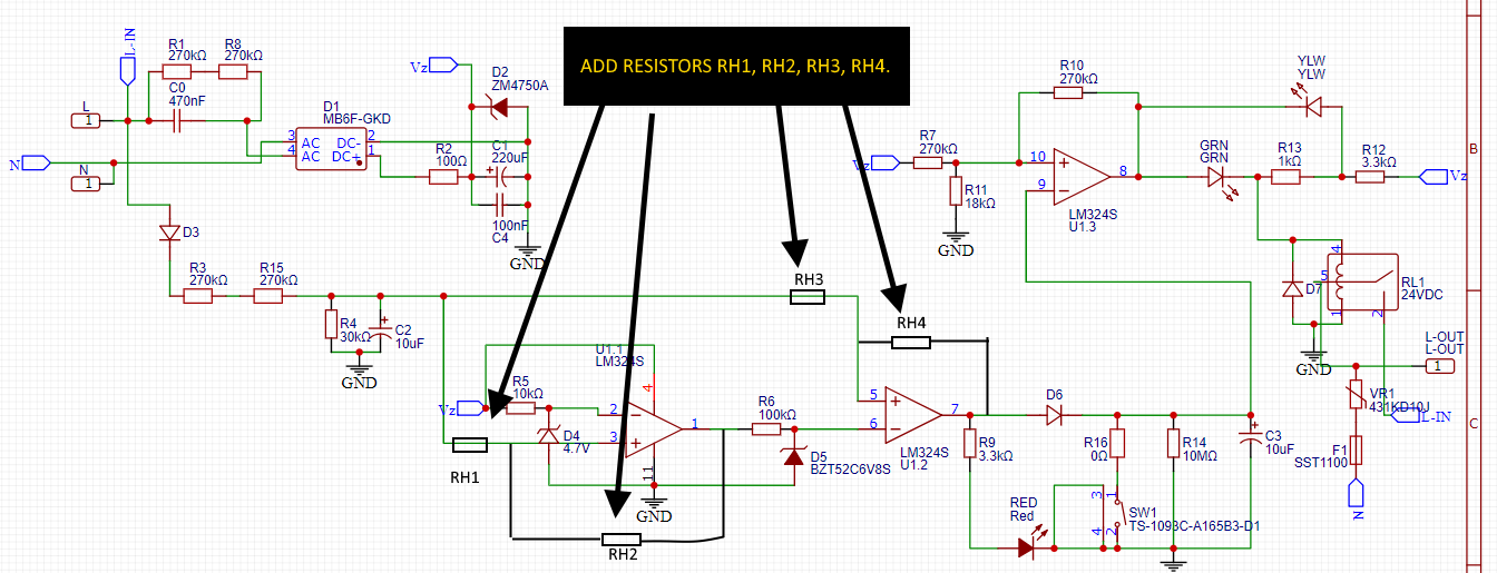
Seems you need what is known as a "window comparator". This is just two separate comparators, each looking at the same input signal and comparing it to separate thresholds, Vlow and Vhigh. This provides two separate outputs: one to tell you if the input is below Vlow, and another to tell you if the input is above Vhigh. The benefit of this compared to your existing design is that you get full control over all the variables involved: you can independently adjust both the threshold and hysteresis for each comparator.
Here is a link to a decent app note for a window comparator:
https://www.ti.com/lit/ug/tidub01/tidub01.pdf
You will note that the schematic in this publication has two problems in your application:
(a) The outputs are connected together. I suggest keeping them separate.
(b) Does not include any hysteresis around each comparator; I would suggest adding a small amount of positive feedback (hysteresis) to ensure stability; say, between 0.1 and 1% should be OK, this depends on precisely where you want the output to trip.
Some simple logic after the comparator outputs can then be used to control the three LEDs and the relay as required.
UPDATE AFTER OP IMPROVED THE QUESTION
Your circuit needs hysteresis on BOTH comparators. So you need to add four (4) new resistors, as shown in the mark-up schematic below:
Here are some values that I suggest you try for each resistor. These are selected based on providing 1% hysteresis for each comparator.
RH1, RH3: 10kΩ
RH2: 10MEG Ω
RH4: 10MEG Ω
NOTE: The op-amp you have used for the comparators (LM324S) may not be sufficiently accurate for this application; the input bias currents (90nA typ, 250nA max) are not insignificant when compared to the currents associated with the hysteresis (~2 uA). This may cause the hysteresis to be very dependent upon the op-amp input current, which is not a tightly controlled parameter.
You can improve this situation by placing a new op-amp as a voltage-follower buffer after C2 to provide a low-impedance for the signal to the window comparator, and reducing the impedance of the signal to each comparator to about 1kΩ (it is now at 40kΩ = R4 + RH1, & RH3) so. This change allows RH2 and RH4 canto be reduced significantly to null out the effects of op-amp input bias current variation. Since
Since the LM324 package contains four (4) op-amps, you should have a spare op-amp available to do this.
If If you don't have a spare op-amp available now, then I suggest re-purposing U1:3 for this role, and replacing U1:3 with some simple transistor logic to drive the outputs (LEDs and Relay) as required from the outputs of the comparators.

