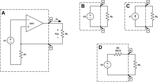
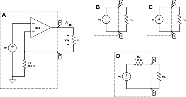
Let's treat the op-amp and its periphery as a "black box", leaving only the load resistor \$R_L\$ outside:

simulate this circuit – Schematic created using CircuitLab
The "black boxes" above each have two terminals, X and Y, and you have no idea what's inside the box. Each box has some internal resistance, which we aim to measure.
We could measure it by changing the external resistance \$R_L\$, or by applying some external potential difference between X and Y, or even by forcing some current through the box. Whatever method we use, we shall measure the resulting change in voltage \$\Delta V_{XY}\$, and change in current \$\Delta I_O\$. Effective resistance \$R_{XY}\$ between X and Y inside the box will be, according to Ohm's law:
$$ R_{XY} = \frac{\Delta V_{XY}}{\Delta I_O} $$
For box B, you'd find that there's no change in voltage, since its internal voltage source will strongly oppose any change in \$V_{XY}\$, but current \$I_O\$ is able to rise and fall freely:
$$ R_{XY(B)} = \frac{\Delta V_{XY}}{\Delta I_O} = \frac{0}{\Delta I_O} = 0\Omega $$
In other words, box B (or any ideal voltage source) is said to have zero impedance.
Box C is a current source, and we would expect it to strongly oppose changes in current through it, \$\Delta I_O=0\$, while freely permitting \$V_{XY}\$ to change:
$$ R_{XY(C)} = \frac{\Delta V_{XY}}{0} = \infty \Omega $$
Ideal current sources, therefore, are said to have infinite source impedance.
Box D will have an impedance somewhere in between zero and infinity, because in this case it would be possible to impose any arbitrary voltage between X and Y, and it's also possible to inject an arbitrary current through the box. With either "perturbation" method, if you plotted \$I_O\$ on the horizontal axis, vs. its corresponding \$V_{XY}\$, the slope of that graph is \$R_{XY}\$. Just by inspection, you could predict that this slope would be:
$$ R_{XY(D)} = \frac{\Delta V_{XY}}{\Delta I_O} = 100\Omega $$
SoFor more information, and a graphical treatment of using voltage and current changes, and the slope of the characteristic V-I graph to represent impedance, see this answer.
To answer your question, it remains to be determined which of the boxes B, C and D has behaviour which most closely resembles the behaviour of box A.
We are permitted to attach any load \$R_L\$ we desire and you could even apply some arbitrary potential difference between X and Y, and it would still keep \$I_O\$ constant. The op-amp will adjust \$V_{XY}\$ to whatever value is necessary to keep \$I_O\$ fixed. Thus \$\Delta I_O = 0\$, so:
$$ R_{XY(A)} = \frac{\Delta V_{XY}}{0} = \infty \Omega $$
This is consistent with the behaviour of the ideal current source in box C.
It's true that the op-amp is indeed a voltage source, using voltages to obtain this behaviour, but in the context of a two-terminal "black box", for which we only have access to the exposed terminals, nodes X and Y, any external "observer" circuitry would perceive it to behave like a current source, for which the impedance inside the box is effectively infinite. No amount of voltage applied, and no impedance of load attached (op-amp constraints notwithstanding, such as limited output voltage range and current limits) will result in a change in \$I_O\$.

