deleted 14 characters in body; edited title
Source Link
winny
  • 16.8k
  • 6
  • 50
  • 71

LTspice issues with Amp Opop-amp filter

I need to simulate in LTspice a wattmeter connected to a 800V800 V DC/DC converter (step-down) with silicon carbide (SiC) transistors. The wattmeter measures the voltage across the lower transistor (V_out) and the inductor current, but we'll focus on V_out for my question. The goal is to study the differences before and after the filter, to calculate losses in the semiconductors in a real experiment.

The wattmeter is simply modeled as a Bessel low-pass filter (cuttcut-off frequency of 150 kHz approx.). I know the transfer function of the filter.

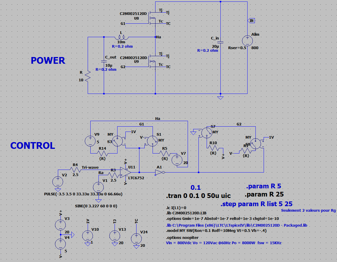
The DC/DC converter has yet been modelized and the simulation works well. enter image description here This simulation comes from the SiC transistors manufacturer's website. The simulation parameters have been optimized. V_out (Ha potential) looks like a square wave, with oscillations and overshoots caused by commutations.
First, I've tried to create the filter using a "voltage controlled voltage source", where I put the Laplace function  : enter image description here

I integrated this filter in the DC/DC converter simulation and it seemed to work nicely  :

enter image description here

But if we look closely to the 2 signals after a time long enough after a commutation, there is a static error of 400 mV between them. Which is weird because the gain of the transfer function is equal to 1.

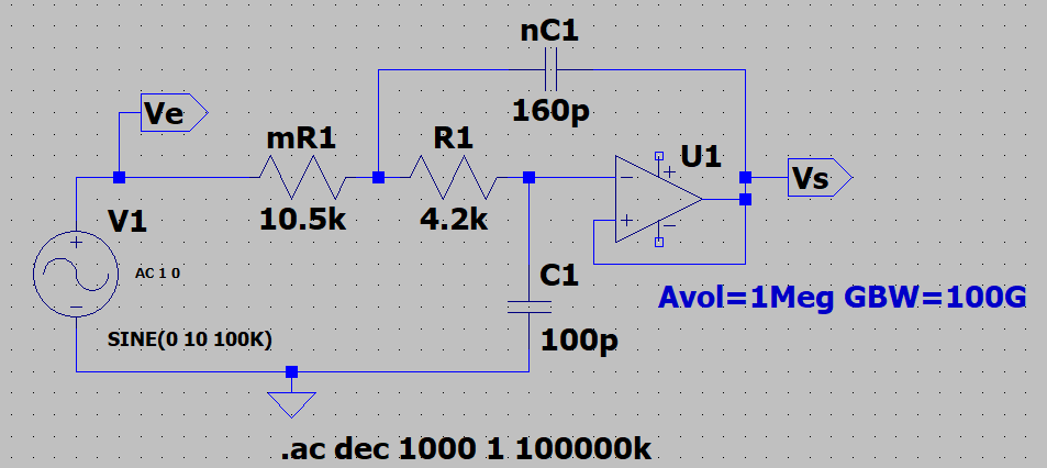
So, I tried to model the filter using an amp-op (Sallen-Key topology)  :

enter image description here

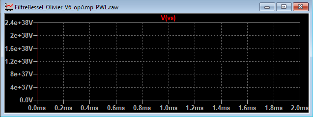
In the simulation, I choose an ideal Op-Amp level 1 (parameters  : Avol=1Meg ; GBW=100G ; Vos=0 ; En=0 ; Enk=0 ; Ink=0 ;Avol=1Meg; GBW=100G; Vos=0; En=0; Enk=0; Ink=0; Rin=500Meg). This filter works well with an ideal square voltage source, but it doesn’t work at all when I connect the filter to the DC/DC converter. The simulation has become infinitely slow (simulation speed around 1 femtos/s). Then, I simulate the converter alone, without the filter, and I saved V_out in a file, using “export data as text”. I opened a new simulation, with the filter connected to a PWL voltage source which received the text file. The simulation runs but the output voltage of the filter is wrong - infinite :

enter image description here

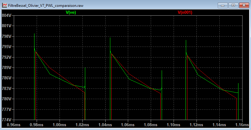
And there is another issue  : the PWL signal is not exactly the same that the signal which was used to create the text file  :

enter image description here

I would really appreciate your help and I thank you in advance. If my problem is unclear, I can reformulate. Sorry for my English...

PS  : I sometimes get errors like "Singular matric  : check nodes xxx and yyy iteration no.2"

LTspice issues with Amp Op filter

I need to simulate in LTspice a wattmeter connected to a 800V DC/DC converter (step-down) with silicon carbide (SiC) transistors. The wattmeter measures the voltage across the lower transistor (V_out) and the inductor current, but we'll focus on V_out for my question. The goal is to study the differences before and after the filter, to calculate losses in the semiconductors in a real experiment.

The wattmeter is simply modeled as a Bessel low-pass filter (cutt-off frequency of 150 kHz approx.). I know the transfer function of the filter.

The DC/DC converter has yet been modelized and the simulation works well. enter image description here This simulation comes from the SiC transistors manufacturer's website. The simulation parameters have been optimized. V_out (Ha potential) looks like a square wave, with oscillations and overshoots caused by commutations.

First, I've tried to create the filter using a "voltage controlled voltage source", where I put the Laplace function  : enter image description here

I integrated this filter in the DC/DC converter simulation and it seemed to work nicely  :

enter image description here

But if we look closely to the 2 signals after a time long enough after a commutation, there is a static error of 400 mV between them. Which is weird because the gain of the transfer function is equal to 1.

So, I tried to model the filter using an amp-op (Sallen-Key topology)  :

enter image description here

In the simulation, I choose an ideal Op-Amp level 1 (parameters  : Avol=1Meg ; GBW=100G ; Vos=0 ; En=0 ; Enk=0 ; Ink=0 ; Rin=500Meg). This filter works well with an ideal square voltage source, but it doesn’t work at all when I connect the filter to the DC/DC converter. The simulation has become infinitely slow (simulation speed around 1 femtos/s). Then, I simulate the converter alone, without the filter, and I saved V_out in a file, using “export data as text”. I opened a new simulation, with the filter connected to a PWL voltage source which received the text file. The simulation runs but the output voltage of the filter is wrong - infinite :

enter image description here

And there is another issue  : the PWL signal is not exactly the same that the signal which was used to create the text file  :

enter image description here

I would really appreciate your help and I thank you in advance. If my problem is unclear, I can reformulate. Sorry for my English...

PS  : I sometimes get errors like "Singular matric  : check nodes xxx and yyy iteration no.2"
LTspice issues with op-amp filter

I need to simulate in LTspice a wattmeter connected to a 800 V DC/DC converter (step-down) with silicon carbide (SiC) transistors. The wattmeter measures the voltage across the lower transistor (V_out) and the inductor current, but we'll focus on V_out for my question. The goal is to study the differences before and after the filter, to calculate losses in the semiconductors in a real experiment.

The wattmeter is simply modeled as a Bessel low-pass filter (cut-off frequency of 150 kHz approx.). I know the transfer function of the filter.

The DC/DC converter has yet been modelized and the simulation works well. enter image description here This simulation comes from the SiC transistors manufacturer's website. The simulation parameters have been optimized. V_out (Ha potential) looks like a square wave, with oscillations and overshoots caused by commutations.

First, I've tried to create the filter using a "voltage controlled voltage source", where I put the Laplace function: enter image description here

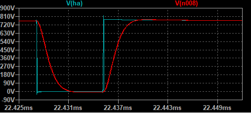
I integrated this filter in the DC/DC converter simulation and it seemed to work nicely:

enter image description here

But if we look closely to the 2 signals after a time long enough after a commutation, there is a static error of 400 mV between them. Which is weird because the gain of the transfer function is equal to 1.

So, I tried to model the filter using an amp-op (Sallen-Key topology):

enter image description here

In the simulation, I choose an ideal Op-Amp level 1 (parameters: Avol=1Meg; GBW=100G; Vos=0; En=0; Enk=0; Ink=0; Rin=500Meg). This filter works well with an ideal square voltage source, but it doesn’t work at all when I connect the filter to the DC/DC converter. The simulation has become infinitely slow (simulation speed around 1 femtos/s). Then, I simulate the converter alone, without the filter, and I saved V_out in a file, using “export data as text”. I opened a new simulation, with the filter connected to a PWL voltage source which received the text file. The simulation runs but the output voltage of the filter is wrong - infinite :

enter image description here

And there is another issue: the PWL signal is not exactly the same that the signal which was used to create the text file:

enter image description here

I would really appreciate your help and I thank you in advance. If my problem is unclear, I can reformulate. Sorry for my English...

PS: I sometimes get errors like "Singular matric: check nodes xxx and yyy iteration no.2"
Source Link

LTspice issues with Amp Op filter

I need to simulate in LTspice a wattmeter connected to a 800V DC/DC converter (step-down) with silicon carbide (SiC) transistors. The wattmeter measures the voltage across the lower transistor (V_out) and the inductor current, but we'll focus on V_out for my question. The goal is to study the differences before and after the filter, to calculate losses in the semiconductors in a real experiment.

The wattmeter is simply modeled as a Bessel low-pass filter (cutt-off frequency of 150 kHz approx.). I know the transfer function of the filter.

The DC/DC converter has yet been modelized and the simulation works well. enter image description here This simulation comes from the SiC transistors manufacturer's website. The simulation parameters have been optimized. V_out (Ha potential) looks like a square wave, with oscillations and overshoots caused by commutations.

First, I've tried to create the filter using a "voltage controlled voltage source", where I put the Laplace function : enter image description here

I integrated this filter in the DC/DC converter simulation and it seemed to work nicely :

enter image description here

But if we look closely to the 2 signals after a time long enough after a commutation, there is a static error of 400 mV between them. Which is weird because the gain of the transfer function is equal to 1.

So, I tried to model the filter using an amp-op (Sallen-Key topology) :

enter image description here

In the simulation, I choose an ideal Op-Amp level 1 (parameters : Avol=1Meg ; GBW=100G ; Vos=0 ; En=0 ; Enk=0 ; Ink=0 ; Rin=500Meg). This filter works well with an ideal square voltage source, but it doesn’t work at all when I connect the filter to the DC/DC converter. The simulation has become infinitely slow (simulation speed around 1 femtos/s). Then, I simulate the converter alone, without the filter, and I saved V_out in a file, using “export data as text”. I opened a new simulation, with the filter connected to a PWL voltage source which received the text file. The simulation runs but the output voltage of the filter is wrong - infinite :

enter image description here

And there is another issue : the PWL signal is not exactly the same that the signal which was used to create the text file :

enter image description here

I would really appreciate your help and I thank you in advance. If my problem is unclear, I can reformulate. Sorry for my English...

PS : I sometimes get errors like "Singular matric : check nodes xxx and yyy iteration no.2"