Your assumption is wrong; LTspice is correct. A negative power value indicates power being returned to the circuit from the device; a capacitor or inductor discharging stored energy.
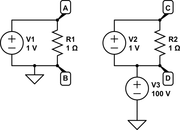
In general, for any device, \$\sum_n \mathrm{V}(n)·\mathrm{I_x}(n)\$ (where \$\mathrm{V}(n)\$ is the voltage at pin \$n\$ relative to an arbitrary (but consistent) reference, and \$\mathrm{I_x}(n)\$ is the current into pin \$n\$) is a valid formula for calculating the instantaneous power in the device. Proving this is beyond what I'm willing to do this early in the morning, but to get an intuitive feel for it, consider these two circuits:

simulate this circuit – Schematic created using CircuitLab
I think you can agree that the power dissipated in R1 is equal to the power dissipated in R2, right? They are both 1 Ω resistors, and both have 1 V across them. The only difference is what point you call 0 V.
Now, let's consider the resistor on the left. The ground-referenced voltage at pin A is 1 V, and the current into pin A is \$\frac{1\ \mathrm{V}}{1\ \mathrm{Ω}}\$ = 1 A. The ground-referenced voltage at pin B is 0 V, and the current into pin B is -1 A (negative, as positive is defined as into the pin). Now, with the formula from earlier, we get $$\begin{align}\mathrm{P(R1)} &= \mathrm{V(A)}·\mathrm{I_x(A)}+\mathrm{V(B)}·\mathrm{I_x(B)}\\ &= 1\ \mathrm{V}·1\ \mathrm{A} + 0\ \mathrm{V}·-1\ \mathrm{A}\\ &= 1\ \mathrm{W} + 0\ \mathrm{W}\\ &= 1\ \mathrm{W}\end{align}.$$
This, of course, is an excessively complicated way to calculate the power in this resistor, but the general utility in the context of SPICE (which works entirely based on ground-referenced node voltages and branch currents) is clearer when you apply the same logic to the circuit on the right: $$\begin{align}\mathrm{P(R2)} &= \mathrm{V(C)}·\mathrm{I_x(C)}+\mathrm{V(D)}·\mathrm{I_x(D)}\\ &= 101\ \mathrm{V}·1\ \mathrm{A} + 100\ \mathrm{V}·-1\ \mathrm{A}\\ &= 101\ \mathrm{W} - 100\ \mathrm{W}\\ &= 1\ \mathrm{W}\end{align}.$$
Ignoring the current leaving pin D would result in overestimating the power consumption of the resistor by over 100 times!
Note that in this simple two-pin case, this is equivalent to the standard formula for power in a resistor: since \$\mathrm{I_x(A)}=-\mathrm{I_x(B)}\triangleq I\$ by charge conservation, $$\mathrm{V(A)}·\mathrm{I_x(A)}+\mathrm{V(B)}·\mathrm{I_x(B)}\\ = \mathrm{V(A)}·I+\mathrm{V(B)}·-I\\ = \mathrm{V(A)}·I-\mathrm{V(B)}·I\\ = (\mathrm{V(A)}-\mathrm{V(B)})·I,$$ which is the standard formula for power in a resistor.
