added further information
Source Link
Math Keeps Me Busy
  • 27.9k
  • 5
  • 25
  • 87

You did not wire up the voltage source correctly. The negative terminal of the voltage source should be connected to ground, not to OUT.

Here is the circuit with the +5V node replaced by a voltage source V2, and closer to the layout of your circuits.
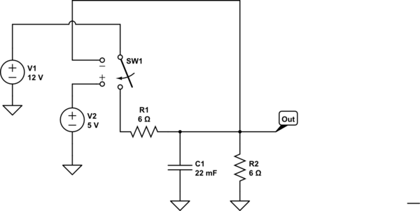
schematic

simulate this circuit – Schematic created using CircuitLab

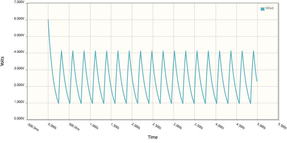
With the parameters for SW1 set at V_T = 2.5 and V_H = 1.5, the output looks like this:

enter image description here

In the edited version of the question, there is a circuit similar to this, but with the parameters for the switch set at Vt = 2.5 and Vh = -0.75. Try changing Vh to 1.5 as in the original circuit.

You did not wire up the voltage source correctly. The negative terminal of the voltage source should be connected to ground, not to OUT.

You did not wire up the voltage source correctly. The negative terminal of the voltage source should be connected to ground, not to OUT.

Here is the circuit with the +5V node replaced by a voltage source V2, and closer to the layout of your circuits.

schematic

simulate this circuit – Schematic created using CircuitLab

With the parameters for SW1 set at V_T = 2.5 and V_H = 1.5, the output looks like this:

enter image description here

In the edited version of the question, there is a circuit similar to this, but with the parameters for the switch set at Vt = 2.5 and Vh = -0.75. Try changing Vh to 1.5 as in the original circuit.

Source Link
Math Keeps Me Busy
  • 27.9k
  • 5
  • 25
  • 87

You did not wire up the voltage source correctly. The negative terminal of the voltage source should be connected to ground, not to OUT.