well i also work on a 400V motor driver but I use AMC1300 IC .you want see some details in data sheet .
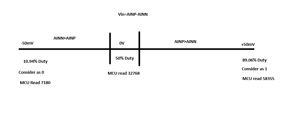
here the long story short . Vin=Ainp-Ainn
INP=0V (Exactly) OP=will give a pulse of 50% duty cycle respect to your frequency.
INP=+50mv(Full scale) OP=1 pulse with 89.06% duty cycle (MCU read as "1" )
INP=-50mv(Full Scale) OP=1 pulse with 10.94% duty cycle (MCU read as "0" )
Clipping mode :
Only Zeros(pulse width 10.96%) are transmitted if input is ≤ –64 mV.
Only Ones (Pulse width 89.06%)are transmitted if input is ≥ +64 mV.
so the consolidated answer is
consider 0V as a center point
If AINP>AINN: Duty cycle is 50% to 89.06% (positive input).
If AINN>AINP: Duty cycle is 50% to 10.94% (negative input).
your assumption is correct.
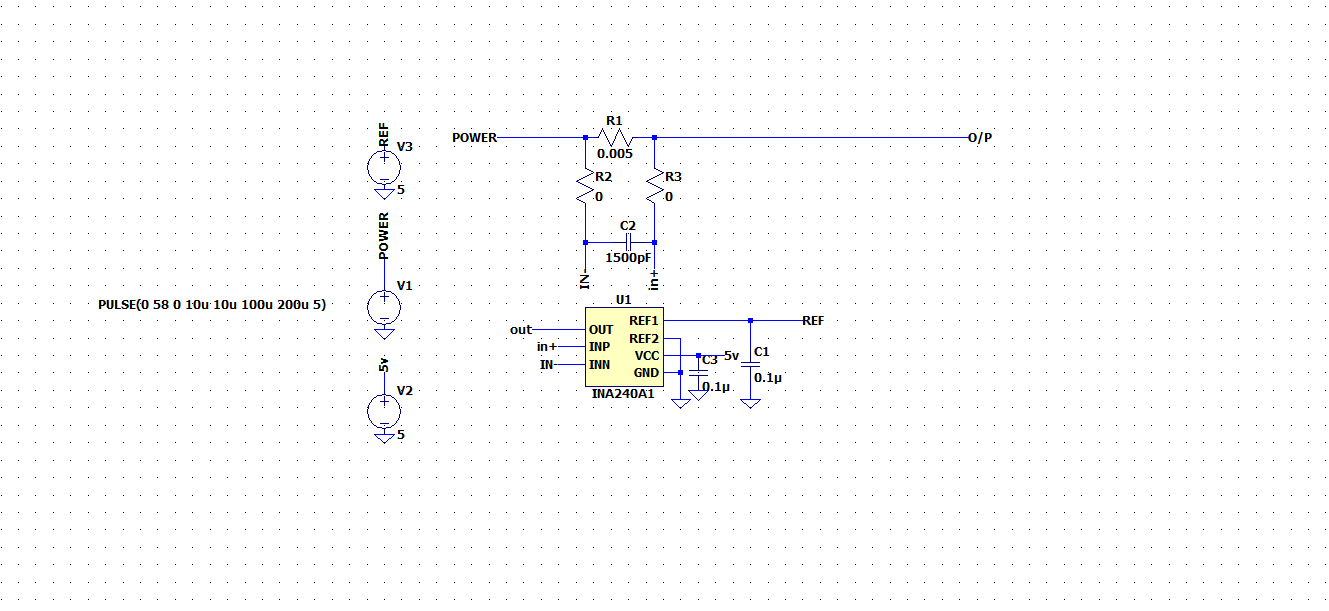
This is the simulation I've done: Actually it has to be done more precisely and the ADC output is read in MCU only.


