added 7 characters in body
Source Link

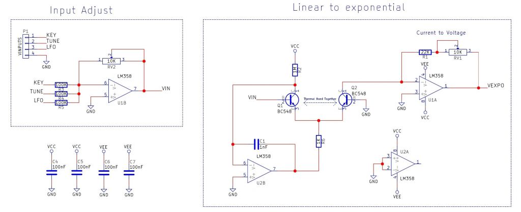
I'm making a VCO for use as a module in a synth. The VCOoscillator part is working fine. I also need to translate a 1v/oct voltage input to a log scaled voltage output in order to get the correct freq out of the VCO. Makes sense. So I built a lin to log circuit as well (2 opamps tied together with emitter), which also works fine. enter image description here
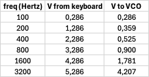
I did some testing with my signalgen and fed the VCO to see what voltage is needed for certain freqs.

enter image description here

enter image description here

In the column V from keyboard is the ideal voltage coming from my keyboard (which in reality gives a 0-5v output). The column V to VCO is the actual voltage needed (as tested with my signalgen) resulting in the correct freqs.

The 2 combined though (VCOOSC and LIN2LOG circuit) dont match up (surprise surprise. I dont want it to be correct over the whole musical range; a normal expected behaviour for a VCO would be 2-3 octave of correct sounding octaves and a pitch knob to set the base freq. Im totally ok with that.

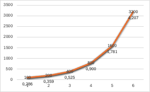
My assumptions: lin to log conversion is what it is. I cannot control the slope (because of the behaviour of the transistors) so I have to focus on the input of things. My idea is to 'scale' the input in such a way that the output curve of the LIN2LOG circuit behaves like my graph.

My question is the following: Am I on the right track here? What is the best place to start looking for the solution? Trying to learn here :-)

I'm making a VCO for use as a module in a synth. The VCO part is working fine. I also need to translate a 1v/oct voltage input to a log scaled voltage output in order to get the correct freq out of the VCO. Makes sense. So I built a lin to log circuit as well (2 opamps tied together with emitter), which also works fine. enter image description here

I did some testing with my signalgen and fed the VCO to see what voltage is needed for certain freqs.

enter image description here

enter image description here

In the column V from keyboard is the ideal voltage coming from my keyboard (which in reality gives a 0-5v output). The column V to VCO is the actual voltage needed (as tested with my signalgen) resulting in the correct freqs.

The 2 combined though (VCO and LIN2LOG circuit) dont match up (surprise surprise. I dont want it to be correct over the whole musical range; a normal expected behaviour for a VCO would be 2-3 octave of correct sounding octaves and a pitch knob to set the base freq. Im totally ok with that.

My assumptions: lin to log conversion is what it is. I cannot control the slope (because of the behaviour of the transistors) so I have to focus on the input of things. My idea is to 'scale' the input in such a way that the output curve of the LIN2LOG circuit behaves like my graph.

My question is the following: Am I on the right track here? What is the best place to start looking for the solution? Trying to learn here :-)
I'm making a VCO for use as a module in a synth. The oscillator part is working fine. I also need to translate a 1v/oct voltage input to a log scaled voltage output in order to get the correct freq out of the VCO. Makes sense. So I built a lin to log circuit as well (2 opamps tied together with emitter), which also works fine. enter image description here

I did some testing with my signalgen and fed the VCO to see what voltage is needed for certain freqs.

enter image description here

enter image description here

In the column V from keyboard is the ideal voltage coming from my keyboard (which in reality gives a 0-5v output). The column V to VCO is the actual voltage needed (as tested with my signalgen) resulting in the correct freqs.

The 2 combined though (OSC and LIN2LOG circuit) dont match up (surprise surprise. I dont want it to be correct over the whole musical range; a normal expected behaviour for a VCO would be 2-3 octave of correct sounding octaves and a pitch knob to set the base freq. Im totally ok with that.

My assumptions: lin to log conversion is what it is. I cannot control the slope (because of the behaviour of the transistors) so I have to focus on the input of things. My idea is to 'scale' the input in such a way that the output curve of the LIN2LOG circuit behaves like my graph.

My question is the following: Am I on the right track here? What is the best place to start looking for the solution? Trying to learn here :-)

Source Link

Linear to log opamp transisor setup

I'm making a VCO for use as a module in a synth. The VCO part is working fine. I also need to translate a 1v/oct voltage input to a log scaled voltage output in order to get the correct freq out of the VCO. Makes sense. So I built a lin to log circuit as well (2 opamps tied together with emitter), which also works fine. enter image description here

I did some testing with my signalgen and fed the VCO to see what voltage is needed for certain freqs.

enter image description here

enter image description here

In the column V from keyboard is the ideal voltage coming from my keyboard (which in reality gives a 0-5v output). The column V to VCO is the actual voltage needed (as tested with my signalgen) resulting in the correct freqs.

The 2 combined though (VCO and LIN2LOG circuit) dont match up (surprise surprise. I dont want it to be correct over the whole musical range; a normal expected behaviour for a VCO would be 2-3 octave of correct sounding octaves and a pitch knob to set the base freq. Im totally ok with that.

My assumptions: lin to log conversion is what it is. I cannot control the slope (because of the behaviour of the transistors) so I have to focus on the input of things. My idea is to 'scale' the input in such a way that the output curve of the LIN2LOG circuit behaves like my graph.

My question is the following: Am I on the right track here? What is the best place to start looking for the solution? Trying to learn here :-)