added 53 characters in body
Source Link
aaab
  • 25
  • 3

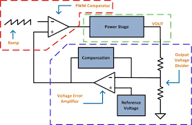
I am trying to build a PWM controller as shown in the figure below. Considering the example that my input is 5V and output is 10V and I need a duty cycle of 50%. enter image description here
Ref for image: https://i.sstatic.net/0kkWg3nC.png

My doubt was what happens once the output is 10V and the error is zero? Would the output of the error amplifier be zero? In that case then the comparator output would also be zero and there would be no regulation right? What am I missing here?

I am trying to build a PWM controller as shown in the figure below. Considering the example that my input is 5V and output is 10V and I need a duty cycle of 50%. enter image description here

Ref for image: https://i.sstatic.net/0kkWg3nC.png

My doubt was what happens once the output is 10V and the error is zero? Would the output of the error amplifier be zero? In that case then the comparator output would also be zero and there would be no regulation right? What am I missing here?

Source Link
aaab
  • 25
  • 3

Fundamental question regarding the working of a PWM voltage mode controller in SMPS

I am trying to build a PWM controller as shown in the figure below. Considering the example that my input is 5V and output is 10V and I need a duty cycle of 50%. enter image description here

My doubt was what happens once the output is 10V and the error is zero? Would the output of the error amplifier be zero? In that case then the comparator output would also be zero and there would be no regulation right? What am I missing here?