Rollback to Revision 2
Source Link
Andy aka
  • 472.9k
  • 29
  • 383
  • 839

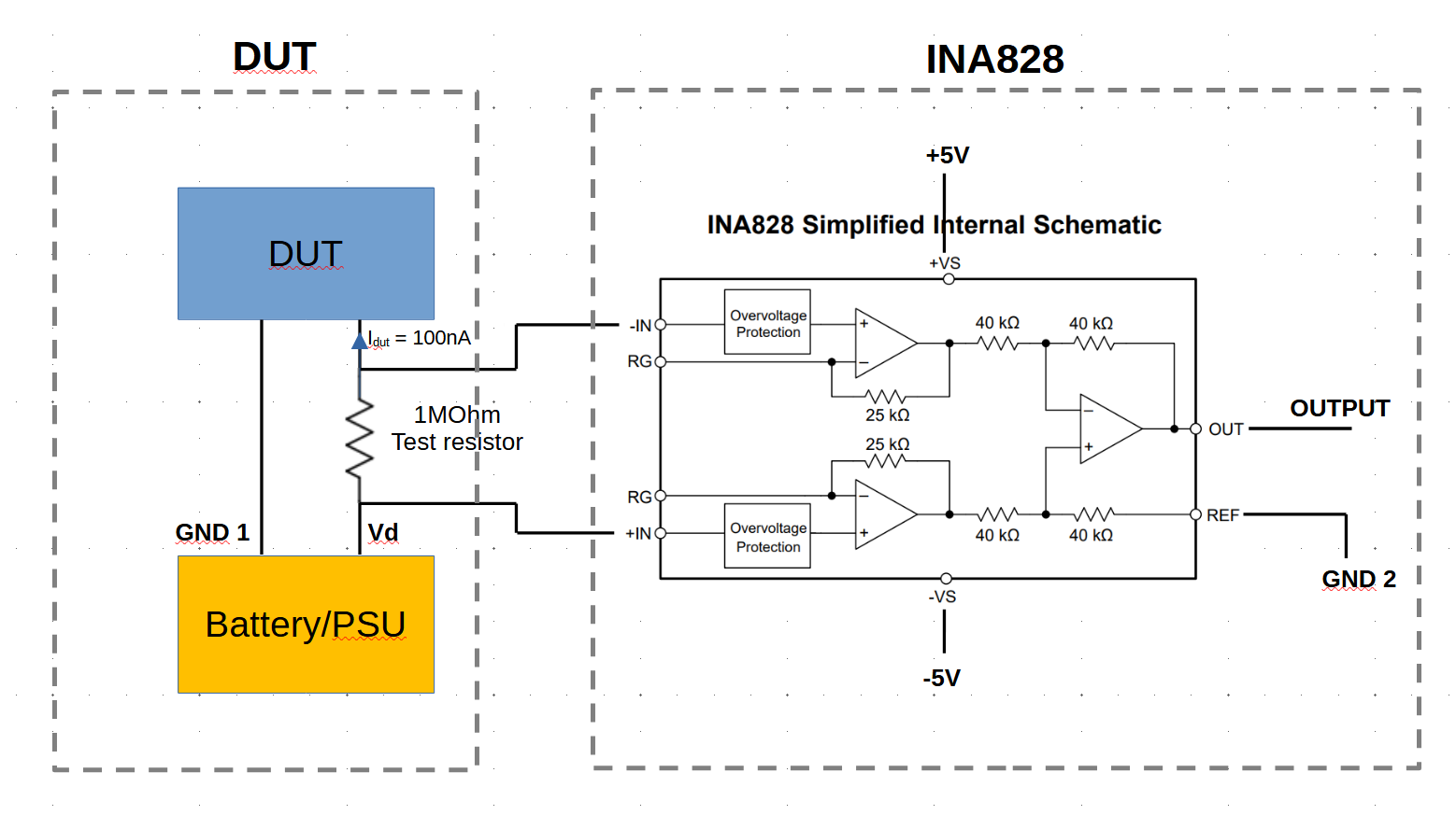
I need to measure the voltage drop across a test resistor in order to sense the current flowing through it. This test resistor has a value of 1 MOhm and it's connected between the positive voltage of a battery (or PSU) and the positive input bias pin of a DUT. The ground pin of the battery (GND1) is connected directly to the ground pin of the DUT (GND1). The current flowing in the resistor is around 50nA to 100nA, thus the voltage across the resistor is about 50mV to 100mV.

I cannot connect directly the test resistor to an ADC to measure the voltage drop across the resistor because the ADC has a low input resistance. I am therefore thinking of using the INA828 between this test resistor and an ADC (for instance the ADS1263).

I am hence thinking to realize something like the schematic below. The ground of the circuit containing DUT (GND1), battery and test resistor will not be common with the ground of the INA828 (GND2) and subsequent ADC. I have some questions:

  1. Do you think the schematic is correct or am I making any mistake?
  2. Is the INA828 a good choice for measuring these voltages or you have a better suggestion? My guess is that it should work well since the input bias current is 0.15nA thus negligible compared to the current flowing in the test resistor.
  3. Do you agree with using a dual supply +/- 5V and to connect the REF pin to ground?
  4. Will I need to use an ADC compatible with dual supply? My guess is that, since the current between battery and DUT will flow only in one direction, the output of the INA828 will be always positive. Or am I wrong?

Thanks in advance

Schematic of the Sensing resistor and INA828

Proposal 2:

Based on comments I received so far I thought a new version of the circuit. This time, there is only a single ground. The REF pin of the INA828 is connected to the common ground GND. The sense resistor is connected between DUT and ground. In this way the difference between common mode voltage and output voltage will be much smaller and should hopefully avoid saturation in the INA828 since the voltage across the sense resistor will be not more than few hundreds of mV.

enter image description here

I need to measure the voltage drop across a test resistor in order to sense the current flowing through it. This test resistor has a value of 1 MOhm and it's connected between the positive voltage of a battery (or PSU) and the positive input bias pin of a DUT. The ground pin of the battery (GND1) is connected directly to the ground pin of the DUT (GND1). The current flowing in the resistor is around 50nA to 100nA, thus the voltage across the resistor is about 50mV to 100mV.

I cannot connect directly the test resistor to an ADC to measure the voltage drop across the resistor because the ADC has a low input resistance. I am therefore thinking of using the INA828 between this test resistor and an ADC (for instance the ADS1263).

I am hence thinking to realize something like the schematic below. The ground of the circuit containing DUT (GND1), battery and test resistor will not be common with the ground of the INA828 (GND2) and subsequent ADC. I have some questions:

  1. Do you think the schematic is correct or am I making any mistake?
  2. Is the INA828 a good choice for measuring these voltages or you have a better suggestion? My guess is that it should work well since the input bias current is 0.15nA thus negligible compared to the current flowing in the test resistor.
  3. Do you agree with using a dual supply +/- 5V and to connect the REF pin to ground?
  4. Will I need to use an ADC compatible with dual supply? My guess is that, since the current between battery and DUT will flow only in one direction, the output of the INA828 will be always positive. Or am I wrong?

Thanks in advance

Schematic of the Sensing resistor and INA828

Proposal 2:

Based on comments I received so far I thought a new version of the circuit. This time, there is only a single ground. The REF pin of the INA828 is connected to the common ground GND. The sense resistor is connected between DUT and ground. In this way the difference between common mode voltage and output voltage will be much smaller and should hopefully avoid saturation in the INA828 since the voltage across the sense resistor will be not more than few hundreds of mV.

enter image description here

I need to measure the voltage drop across a test resistor in order to sense the current flowing through it. This test resistor has a value of 1 MOhm and it's connected between the positive voltage of a battery (or PSU) and the positive input bias pin of a DUT. The ground pin of the battery (GND1) is connected directly to the ground pin of the DUT (GND1). The current flowing in the resistor is around 50nA to 100nA, thus the voltage across the resistor is about 50mV to 100mV.

I cannot connect directly the test resistor to an ADC to measure the voltage drop across the resistor because the ADC has a low input resistance. I am therefore thinking of using the INA828 between this test resistor and an ADC (for instance the ADS1263).

I am hence thinking to realize something like the schematic below. The ground of the circuit containing DUT (GND1), battery and test resistor will not be common with the ground of the INA828 (GND2) and subsequent ADC. I have some questions:

  1. Do you think the schematic is correct or am I making any mistake?
  2. Is the INA828 a good choice for measuring these voltages or you have a better suggestion? My guess is that it should work well since the input bias current is 0.15nA thus negligible compared to the current flowing in the test resistor.
  3. Do you agree with using a dual supply +/- 5V and to connect the REF pin to ground?
  4. Will I need to use an ADC compatible with dual supply? My guess is that, since the current between battery and DUT will flow only in one direction, the output of the INA828 will be always positive. Or am I wrong?

Thanks in advance

Schematic of the Sensing resistor and INA828

Rollback to Revision 3
Source Link
Andy aka
  • 472.9k
  • 29
  • 383
  • 839

I need to measure the voltage drop across a test resistor in order to sense the current flowing through it. This test resistor has a value of 1 MOhm and it's connected between the positive voltage of a battery (or PSU) and the positive input bias pin of a DUT. The ground pin of the battery (GND1) is connected directly to the ground pin of the DUT (GND1). The current flowing in the resistor is around 50nA to 100nA, thus the voltage across the resistor is about 50mV to 100mV.

I cannot connect directly the test resistor to an ADC to measure the voltage drop across the resistor because the ADC has a low input resistance. I am therefore thinking of using the INA828 between this test resistor and an ADC (for instance the ADS1263).

I am hence thinking to realize something like the schematic below. The ground of the circuit containing DUT (GND1), battery and test resistor will not be common with the ground of the INA828 (GND2) and subsequent ADC. I have some questions:

  1. Do you think the schematic is correct or am I making any mistake?
  2. Is the INA828 a good choice for measuring these voltages or you have a better suggestion? My guess is that it should work well since the input bias current is 0.15nA thus negligible compared to the current flowing in the test resistor.
  3. Do you agree with using a dual supply +/- 5V and to connect the REF pin to ground?
  4. Will I need to use an ADC compatible with dual supply? My guess is that, since the current between battery and DUT will flow only in one direction, the output of the INA828 will be always positive. Or am I wrong?

Thanks in advance

Schematic of the Sensing resistor and INA828

Proposal 2:

Based on comments I received so far I thought a new version of the circuit. This time, there is only a single ground. The REF pin of the INA828 is connected to the common ground GND. The sense resistor is connected between DUT and ground. In this way the difference between common mode voltage and output voltage will be much smaller and should hopefully avoid saturation in the INA828 since the voltage across the sense resistor will be not more than few hundreds of mV. The +5V, -5V dual supply is generated by two 9V batteries (to get +9V, -9V) in combination with a positive LDO and a negative LDO to convert to a "stable" +5V, -5V.

enter image description here

I need to measure the voltage drop across a test resistor in order to sense the current flowing through it. This test resistor has a value of 1 MOhm and it's connected between the positive voltage of a battery (or PSU) and the positive input bias pin of a DUT. The ground pin of the battery (GND1) is connected directly to the ground pin of the DUT (GND1). The current flowing in the resistor is around 50nA to 100nA, thus the voltage across the resistor is about 50mV to 100mV.

I cannot connect directly the test resistor to an ADC to measure the voltage drop across the resistor because the ADC has a low input resistance. I am therefore thinking of using the INA828 between this test resistor and an ADC (for instance the ADS1263).

I am hence thinking to realize something like the schematic below. The ground of the circuit containing DUT (GND1), battery and test resistor will not be common with the ground of the INA828 (GND2) and subsequent ADC. I have some questions:

  1. Do you think the schematic is correct or am I making any mistake?
  2. Is the INA828 a good choice for measuring these voltages or you have a better suggestion? My guess is that it should work well since the input bias current is 0.15nA thus negligible compared to the current flowing in the test resistor.
  3. Do you agree with using a dual supply +/- 5V and to connect the REF pin to ground?
  4. Will I need to use an ADC compatible with dual supply? My guess is that, since the current between battery and DUT will flow only in one direction, the output of the INA828 will be always positive. Or am I wrong?

Thanks in advance

Schematic of the Sensing resistor and INA828

Proposal 2:

Based on comments I received so far I thought a new version of the circuit. This time, there is only a single ground. The REF pin of the INA828 is connected to the common ground GND. The sense resistor is connected between DUT and ground. In this way the difference between common mode voltage and output voltage will be much smaller and should hopefully avoid saturation in the INA828 since the voltage across the sense resistor will be not more than few hundreds of mV.

enter image description here

added 165 characters in body
Source Link

I need to measure the voltage drop across a test resistor in order to sense the current flowing through it. This test resistor has a value of 1 MOhm and it's connected between the positive voltage of a battery (or PSU) and the positive input bias pin of a DUT. The ground pin of the battery (GND1) is connected directly to the ground pin of the DUT (GND1). The current flowing in the resistor is around 50nA to 100nA, thus the voltage across the resistor is about 50mV to 100mV.

I cannot connect directly the test resistor to an ADC to measure the voltage drop across the resistor because the ADC has a low input resistance. I am therefore thinking of using the INA828 between this test resistor and an ADC (for instance the ADS1263).

I am hence thinking to realize something like the schematic below. The ground of the circuit containing DUT (GND1), battery and test resistor will not be common with the ground of the INA828 (GND2) and subsequent ADC. I have some questions:

  1. Do you think the schematic is correct or am I making any mistake?
  2. Is the INA828 a good choice for measuring these voltages or you have a better suggestion? My guess is that it should work well since the input bias current is 0.15nA thus negligible compared to the current flowing in the test resistor.
  3. Do you agree with using a dual supply +/- 5V and to connect the REF pin to ground?
  4. Will I need to use an ADC compatible with dual supply? My guess is that, since the current between battery and DUT will flow only in one direction, the output of the INA828 will be always positive. Or am I wrong?

Thanks in advance

Schematic of the Sensing resistor and INA828

Proposal 2:

Based on comments I received so far I thought a new version of the circuit. This time, there is only a single ground. The REF pin of the INA828 is connected to the common ground GND. The sense resistor is connected between DUT and ground. In this way the difference between common mode voltage and output voltage will be much smaller and should hopefully avoid saturation in the INA828 since the voltage across the sense resistor will be not more than few hundreds of mV. The +5V, -5V dual supply is generated by two 9V batteries (to get +9V, -9V) in combination with a positive LDO and a negative LDO to convert to a "stable" +5V, -5V.

enter image description here

I need to measure the voltage drop across a test resistor in order to sense the current flowing through it. This test resistor has a value of 1 MOhm and it's connected between the positive voltage of a battery (or PSU) and the positive input bias pin of a DUT. The ground pin of the battery (GND1) is connected directly to the ground pin of the DUT (GND1). The current flowing in the resistor is around 50nA to 100nA, thus the voltage across the resistor is about 50mV to 100mV.

I cannot connect directly the test resistor to an ADC to measure the voltage drop across the resistor because the ADC has a low input resistance. I am therefore thinking of using the INA828 between this test resistor and an ADC (for instance the ADS1263).

I am hence thinking to realize something like the schematic below. The ground of the circuit containing DUT (GND1), battery and test resistor will not be common with the ground of the INA828 (GND2) and subsequent ADC. I have some questions:

  1. Do you think the schematic is correct or am I making any mistake?
  2. Is the INA828 a good choice for measuring these voltages or you have a better suggestion? My guess is that it should work well since the input bias current is 0.15nA thus negligible compared to the current flowing in the test resistor.
  3. Do you agree with using a dual supply +/- 5V and to connect the REF pin to ground?
  4. Will I need to use an ADC compatible with dual supply? My guess is that, since the current between battery and DUT will flow only in one direction, the output of the INA828 will be always positive. Or am I wrong?

Thanks in advance

Schematic of the Sensing resistor and INA828

Proposal 2:

Based on comments I received so far I thought a new version of the circuit. This time, there is only a single ground. The REF pin of the INA828 is connected to the common ground GND. The sense resistor is connected between DUT and ground. In this way the difference between common mode voltage and output voltage will be much smaller and should hopefully avoid saturation in the INA828 since the voltage across the sense resistor will be not more than few hundreds of mV.

enter image description here

I need to measure the voltage drop across a test resistor in order to sense the current flowing through it. This test resistor has a value of 1 MOhm and it's connected between the positive voltage of a battery (or PSU) and the positive input bias pin of a DUT. The ground pin of the battery (GND1) is connected directly to the ground pin of the DUT (GND1). The current flowing in the resistor is around 50nA to 100nA, thus the voltage across the resistor is about 50mV to 100mV.

I cannot connect directly the test resistor to an ADC to measure the voltage drop across the resistor because the ADC has a low input resistance. I am therefore thinking of using the INA828 between this test resistor and an ADC (for instance the ADS1263).

I am hence thinking to realize something like the schematic below. The ground of the circuit containing DUT (GND1), battery and test resistor will not be common with the ground of the INA828 (GND2) and subsequent ADC. I have some questions:

  1. Do you think the schematic is correct or am I making any mistake?
  2. Is the INA828 a good choice for measuring these voltages or you have a better suggestion? My guess is that it should work well since the input bias current is 0.15nA thus negligible compared to the current flowing in the test resistor.
  3. Do you agree with using a dual supply +/- 5V and to connect the REF pin to ground?
  4. Will I need to use an ADC compatible with dual supply? My guess is that, since the current between battery and DUT will flow only in one direction, the output of the INA828 will be always positive. Or am I wrong?

Thanks in advance

Schematic of the Sensing resistor and INA828

Proposal 2:

Based on comments I received so far I thought a new version of the circuit. This time, there is only a single ground. The REF pin of the INA828 is connected to the common ground GND. The sense resistor is connected between DUT and ground. In this way the difference between common mode voltage and output voltage will be much smaller and should hopefully avoid saturation in the INA828 since the voltage across the sense resistor will be not more than few hundreds of mV. The +5V, -5V dual supply is generated by two 9V batteries (to get +9V, -9V) in combination with a positive LDO and a negative LDO to convert to a "stable" +5V, -5V.

enter image description here

added 584 characters in body
Source Link
Loading
edited tags
Link
Loading
Source Link
Loading