added 111 characters in body
Source Link
Phil Frost
  • 57.9k
  • 19
  • 153
  • 270

I'm only going to answer one of your questions. It would be better if you asked your questions separately.

My last is, how does one know what the maximum frequency that one can put into an op-amp is?

This is specified in the datasheet. Applying a frequency beyond the op-amp's specifications won't harm it. The limitation is simply that as frequency increases, the op-amp's gain decreases. Essentially, it is a low-pass filter. The image from your question illustrates this:

frequency response

If your input square wave is very much below the op-amp's cutoff frequency, then it will pass through unchanged. As the cutoff frequency gets closer to the square wave frequency, it begins attenuating the higher harmonics, which has the effect of increasing the rise and fall times. Eventually, all the harmonics will be attenuated, and the square wave will start looking more like a sine wave. As the square wave frequency increases beyond the op-amp's cutoff frequency, the entire signal is attenuated, until you are left with nothing at all.

Here's an animation from Wikipedia showing the shape of the square wave as higher harmonics are added. The process I described is the same thing, but in reverse: the higher harmonics are attenuated.
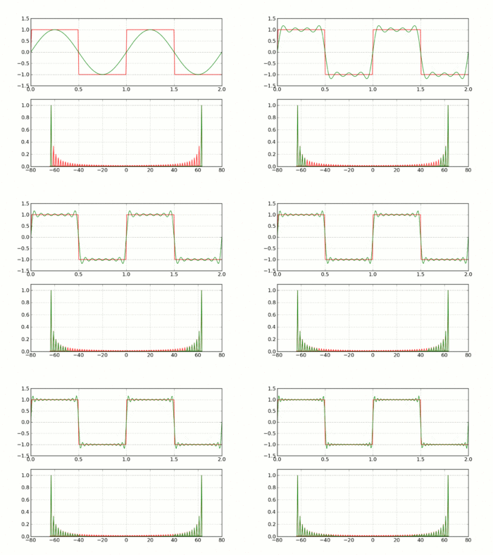
square wave synthesis

I'm only going to answer one of your questions. It would be better if you asked your questions separately.

My last is, how does one know what the maximum frequency that one can put into an op-amp is?

This is specified in the datasheet. Applying a frequency beyond the op-amp's specifications won't harm it. The limitation is simply that as frequency increases, the op-amp's gain decreases. Essentially, it is a low-pass filter. If your input square wave is very much below the op-amp's cutoff frequency, then it will pass through unchanged. As the cutoff frequency gets closer to the square wave frequency, it begins attenuating the higher harmonics, which has the effect of increasing the rise and fall times. Eventually, all the harmonics will be attenuated, and the square wave will start looking more like a sine wave. As the square wave frequency increases beyond the op-amp's cutoff frequency, the entire signal is attenuated, until you are left with nothing at all.

Here's an animation from Wikipedia showing the shape of the square wave as higher harmonics are added. The process I described is the same thing, but in reverse: the higher harmonics are attenuated.

square wave synthesis

I'm only going to answer one of your questions. It would be better if you asked your questions separately.

My last is, how does one know what the maximum frequency that one can put into an op-amp is?

This is specified in the datasheet. Applying a frequency beyond the op-amp's specifications won't harm it. The limitation is simply that as frequency increases, the op-amp's gain decreases. Essentially, it is a low-pass filter. The image from your question illustrates this:

frequency response

If your input square wave is very much below the op-amp's cutoff frequency, then it will pass through unchanged. As the cutoff frequency gets closer to the square wave frequency, it begins attenuating the higher harmonics, which has the effect of increasing the rise and fall times. Eventually, all the harmonics will be attenuated, and the square wave will start looking more like a sine wave. As the square wave frequency increases beyond the op-amp's cutoff frequency, the entire signal is attenuated, until you are left with nothing at all.

Here's an animation from Wikipedia showing the shape of the square wave as higher harmonics are added. The process I described is the same thing, but in reverse: the higher harmonics are attenuated.

square wave synthesis

Remove first answer, because it was wrong (I should read more carefully what is being asked!)
Source Link
Phil Frost
  • 57.9k
  • 19
  • 153
  • 270

I'd like to know why RB is there? (What purpose does it serve and how do you know?)

RB is there to provide a minimum load as required by the LM358 datasheet. If the output is totally open, and the minimum load specification is violated, the LM358 is no longer guaranteed to meets its other specifications. Probably, the output voltage goes up. RB guarantees that some load is always connected.

The second is with regard to the figure below showing open-loop response. I don't quite understand why there is feedback (the cap and the 10M resistor). Could someone please explain why?

I'm notonly going to answer this questionone of your questions. It would be better if you asked your questions separately.

My last is, how does one know what the maximum frequency that one can put into an op-amp is?

This is specified in the datasheet. Applying a frequency beyond the op-amp's specifications won't harm it. The limitation is simply that as frequency increases, the op-amp's gain decreases. Essentially, it is a low-pass filter. If your input square wave is very much below the op-amp's cutoff frequency, then it will pass through unchanged. As the cutoff frequency gets closer to the square wave frequency, it begins attenuating the higher harmonics, which has the effect of increasing the rise and fall times. Eventually, all the harmonics will be attenuated, and the square wave will start looking more like a sine wave. As the square wave frequency increases beyond the op-amp's cutoff frequency, the entire signal is attenuated, until you are left with nothing at all.

Here's an animation from Wikipedia showing the shape of the square wave as higher harmonics are added. The process I described is the same thing, but in reverse: the higher harmonics are attenuated.

square wave synthesis

I'd like to know why RB is there? (What purpose does it serve and how do you know?)

RB is there to provide a minimum load as required by the LM358 datasheet. If the output is totally open, and the minimum load specification is violated, the LM358 is no longer guaranteed to meets its other specifications. Probably, the output voltage goes up. RB guarantees that some load is always connected.

The second is with regard to the figure below showing open-loop response. I don't quite understand why there is feedback (the cap and the 10M resistor). Could someone please explain why?

I'm not going to answer this question. It would be better if you asked your questions separately.

My last is, how does one know what the maximum frequency that one can put into an op-amp is?

This is specified in the datasheet. Applying a frequency beyond the op-amp's specifications won't harm it. The limitation is simply that as frequency increases, the op-amp's gain decreases. Essentially, it is a low-pass filter. If your input square wave is very much below the op-amp's cutoff frequency, then it will pass through unchanged. As the cutoff frequency gets closer to the square wave frequency, it begins attenuating the higher harmonics, which has the effect of increasing the rise and fall times. Eventually, all the harmonics will be attenuated, and the square wave will start looking more like a sine wave. As the square wave frequency increases beyond the op-amp's cutoff frequency, the entire signal is attenuated, until you are left with nothing at all.

Here's an animation from Wikipedia showing the shape of the square wave as higher harmonics are added. The process I described is the same thing, but in reverse: the higher harmonics are attenuated.

square wave synthesis

I'm only going to answer one of your questions. It would be better if you asked your questions separately.

My last is, how does one know what the maximum frequency that one can put into an op-amp is?

This is specified in the datasheet. Applying a frequency beyond the op-amp's specifications won't harm it. The limitation is simply that as frequency increases, the op-amp's gain decreases. Essentially, it is a low-pass filter. If your input square wave is very much below the op-amp's cutoff frequency, then it will pass through unchanged. As the cutoff frequency gets closer to the square wave frequency, it begins attenuating the higher harmonics, which has the effect of increasing the rise and fall times. Eventually, all the harmonics will be attenuated, and the square wave will start looking more like a sine wave. As the square wave frequency increases beyond the op-amp's cutoff frequency, the entire signal is attenuated, until you are left with nothing at all.

Here's an animation from Wikipedia showing the shape of the square wave as higher harmonics are added. The process I described is the same thing, but in reverse: the higher harmonics are attenuated.

square wave synthesis

Source Link
Phil Frost
  • 57.9k
  • 19
  • 153
  • 270

I'd like to know why RB is there? (What purpose does it serve and how do you know?)

RB is there to provide a minimum load as required by the LM358 datasheet. If the output is totally open, and the minimum load specification is violated, the LM358 is no longer guaranteed to meets its other specifications. Probably, the output voltage goes up. RB guarantees that some load is always connected.

The second is with regard to the figure below showing open-loop response. I don't quite understand why there is feedback (the cap and the 10M resistor). Could someone please explain why?

I'm not going to answer this question. It would be better if you asked your questions separately.

My last is, how does one know what the maximum frequency that one can put into an op-amp is?

This is specified in the datasheet. Applying a frequency beyond the op-amp's specifications won't harm it. The limitation is simply that as frequency increases, the op-amp's gain decreases. Essentially, it is a low-pass filter. If your input square wave is very much below the op-amp's cutoff frequency, then it will pass through unchanged. As the cutoff frequency gets closer to the square wave frequency, it begins attenuating the higher harmonics, which has the effect of increasing the rise and fall times. Eventually, all the harmonics will be attenuated, and the square wave will start looking more like a sine wave. As the square wave frequency increases beyond the op-amp's cutoff frequency, the entire signal is attenuated, until you are left with nothing at all.

Here's an animation from Wikipedia showing the shape of the square wave as higher harmonics are added. The process I described is the same thing, but in reverse: the higher harmonics are attenuated.

square wave synthesis