You may want to consider an adaptation of the idea shown here.

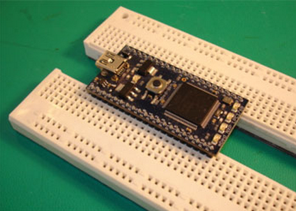
The idea is to split the board down the middle. (A better choice of board is the type that has an open slot down the middle with the sides connected across only in a few places). As seen above the board was split to allow it to efficiently support a wide device without covering up all the adjacent holes.
The modified idea would be to use some sandpaper laid grit side up on a nice flat surface. Then sand the inner edges of the separated board so that they become thin enough that when the two sides are slid next to each other that the rows of holes get close to the 0.1" spacing that you need for a standard dual row header. While sanding use care to hold the pieces upright in a square manner and apply even pressure so that the whole length gets sanded down in an even manner. Sometimes it can be useful to swap the piece end for end several times during the sanding process to even out the variation of pressure on how you hold the part against the sand paper.
You may find that to get the parts sanded enough to achieve the 0.1" spacing that the ends of the metal contact strips may become exposed. If this happens you can over-sand the part by the thickness of piece of plastic electrical tape and then run a strip down the middle to insulate the exposed metal from one side to the other.
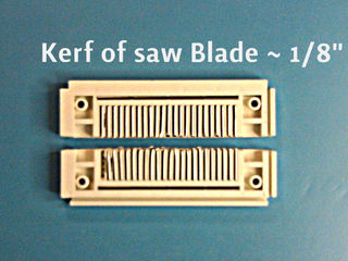
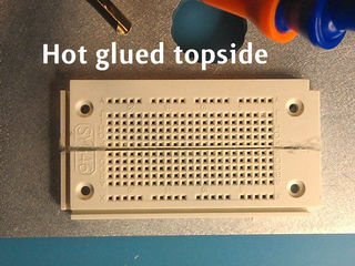
That can be seen in this Instructable, requiring careful cutting (after removing the contacts), insulation, and gluing it back together, a 0.1" spacing is possible.
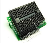
Here is an example of a solderless breadboard that has an open slot down the middle such that there is far less plastic to remove.


