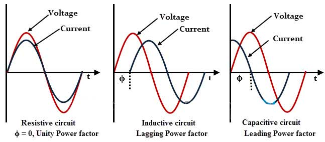
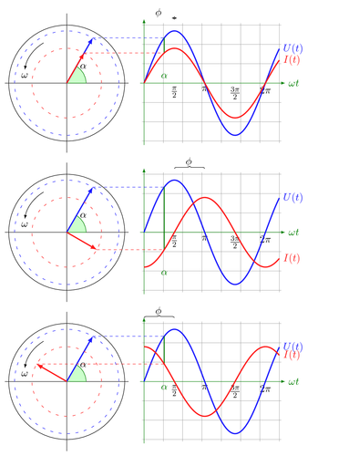
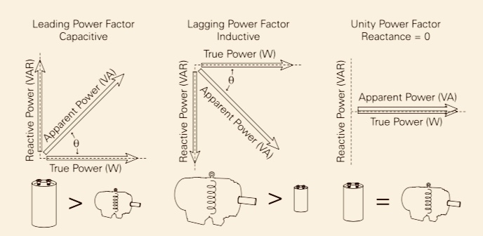
This image should help you understand unity power factor. Which is simply the phase difference between the voltage and the current sinusoids of the system. The photo below shows this in the time domain. You can see unity, leading and lagging power factors caused by balance or imbalance in this phase difference.

However it is also useful to think about this in the phasor domain. Which is the left column in the image below. This allows us to simplify the math to understand how to "achieve" unity power factor. We need to align the voltage and current vectors.

To do so we can either add capacitance into the system or add inductance to the system, depending on the initial system's capacitance or inductance.

Your question title specifically appears to be about how your induction motor will operate in a system with unity power factor. It would rotate optimally. You should research the advantages of power factor correction in a system to understand why.
Now your other questions, why is power factor set to .8 or .9, once again the devices in the system whether they are inductive or capacitive loads will determine the power factor of the system.
The device itself will typically have a power factor rating as well which is how it will contribute to the overall system when it's in use. As you have already pointed out it is usually around .8 or .9, typically lagging, because most of our loads are inductive!
There are a ton of induction motors and machines connected to the US grid for example. Thus the grid typically requires adding reactive power to balance out the more typical inductive loads in the system. This is done to reduce the phase different between the voltage and current sinusoids in the system.


