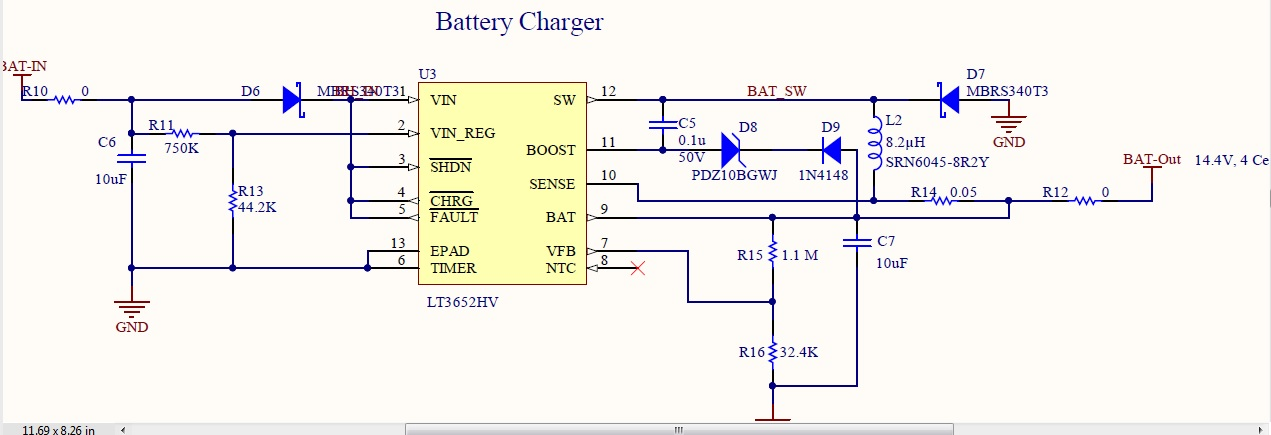
I have designed a battery charging circuit for a lithium ion battery.When i connect a battery the charging IC seems to do nothing. Only when i use a multimeter probe to measure the drop across VFB pin i.e R16 the IC starts to charge,voltage on this pin slowly climbs up to 3.3V like it should. without the meters measurement the IC does not charge the battery.All the components have been checked and is soldered properly. can someone explain what's going on. sorry, i haven't updated schematic .Actual resistor i have used achieves 12.8 float voltage. R15 is 976K, R16 is 340K when i measured across R16 the voltage was 3.22 with battery voltage being 12.6 and it kept increasing towards 3.3 the battery float voltage approaching 12.8, but when i remove the multimeters probe from R16 it stops charging
\$\begingroup\$
\$\endgroup\$
17
-
\$\begingroup\$ You did not report Vfb measured, but it should be 3.3V, which it cannot be with the far too low value of R16. Since R17 is high impedance , your DMM is injecting noise current perhaps. Looks like R16 should move the decimal point over to the right. \$\endgroup\$– D.A.S.Commented Jun 18, 2019 at 7:27
-
\$\begingroup\$ sorry, i haven't updated schematic .Actual resistor i have used achieves 12.8 float voltage. R15 is 976K, R16 is 340K. \$\endgroup\$– JAGADISH KCommented Jun 18, 2019 at 7:31
-
\$\begingroup\$ when i measured across R16 the voltage was 3.22 with battery voltage being 12.6 and it kept increasing towards 3.3 the battery float voltage approaching 12.8, but when i remove the multimeters probe from R16 it stops charging. \$\endgroup\$– JAGADISH KCommented Jun 18, 2019 at 7:35
-
2\$\begingroup\$ actually just caught a possibly big error in your design, pins 4 and 5 are open collector, and they are connected directly to the power supply, the can only sink 10ma, however i couldn't find anything saying its internally limited, meaning that when the circuit starts charging you could well burn it, if you dont intend to use those pins leave them disconnected or grounded, but not at vin \$\endgroup\$– diegogmxCommented Jun 18, 2019 at 10:29
-
1\$\begingroup\$ @diegogmx, your hunch was right. The fault and charging pins cannot be directly connected to VIN, but a current limiting resistor must be used to connect them. I was in touch with Analog devices Engineering support, and they cleared my doubt. Thank's for your help. \$\endgroup\$– JAGADISH KCommented Sep 13, 2019 at 5:43
|
Show 12 more comments
1 Answer
\$\begingroup\$
\$\endgroup\$
@diegogmx's hunch was right(check all the comments). The fault and charging pins cannot be directly connected to VIN, but a current limiting resistor must be used to connect them. I was in touch with Analog devices Engineering support, and they cleared my doubts. Thank's for the help everyone.

