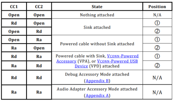
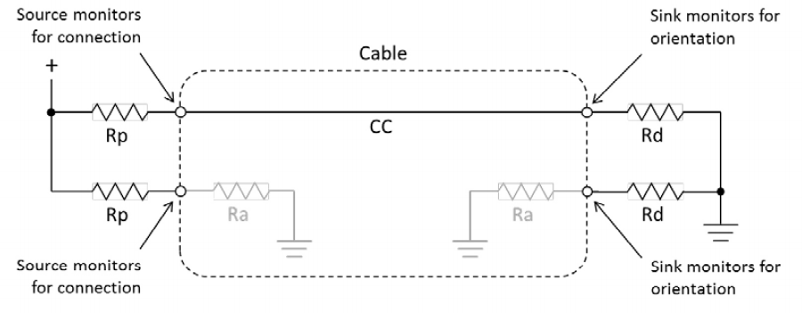
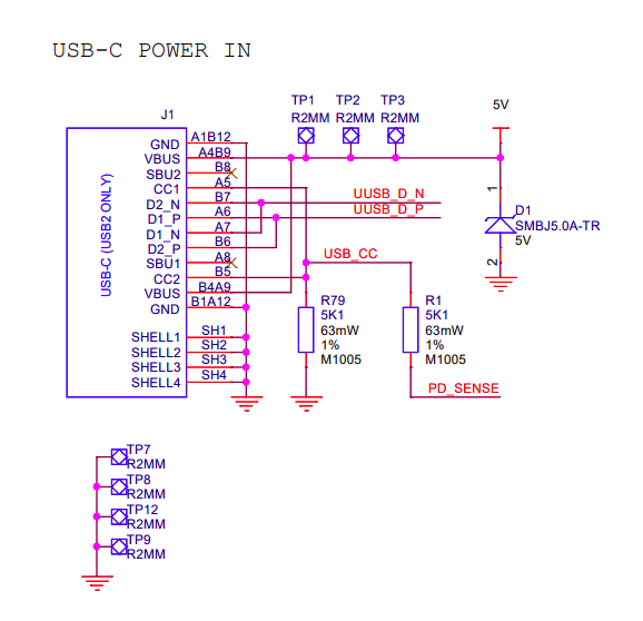
Apparently the problem you are facing has been reported before, and it lies on the pull-down resistors of the Raspberry 4. In short, there should be independent resistors for the CC1 and CC2 lines in order to detect the operating mode according to the following:


Quoting the prossible problem description:
In the correct operation the charger will sense the Rd resistor (Or Rd Ra cobination) and turn on the power. The problem comes when an active cable which presents an Ra at both ends is used. On the source side one CC pin will be connected to the Ra resistor in the cable and the other to the CC line to the Pi. The Pi has connected both lines together so presents the combination of the Ra at the pi end of the cable and the Rd pulldown. Calculating the presented resistance assuming a average value of Ra still gives a value well within the Ra range (also note Ra resistances are permitted to go below 800 when cable electronics are drawing power so a resistance lower than 800 will also likely be detected as Ra).
$$R_{T}=R_a || R_b = 1k\Omega || 5k1\Omega=836\Omega$$
With effectively two Ra values presented to the Source end it will detect the Pi as an “Audio Adaptor Accessory”. These are analogue audio interfaces to allow for headphones to be connected to phones for example (although some phones use headphones/adaptors with inbuilt sound-cards which appear as USB devices). The audio adaptor accessory also allows the phone to be charged through the adaptor. This means the the device should not provide power on the Vbus pins which means no power for the Pi.
Possible solutions
Solution 1:
Assuming the issue you are having is caused by the problem discussed above, using a non e-marked cable (most USB-C phone charger cables are likely this type) rather than an e-marked cable (many laptop charger/thunderbolt cables and any 5A capable cable will be in this category) will allow for the pi to be powered. In addition using older chargers with A-C cables or micro B to C adaptors will also work if they provide enough power as these don’t require CC detection to provide power.
Solution 2(source):
Ultimately though the best solution in the long run will be for there to be a board revision for the pi 4 which adds the 2nd CC resistor and fixes the problem. If you want your USB Type-C devices to work correctly then you need to have two independent CC resistors.
The simplest implementation of this is to use two 5.1k pull down resistors on the CC lines.
This allows for detection by other devices when using a USB C-C cable.
The USB 2.0 Data lines can both be connected together at the receptacle as only one pair will be populated in the connector.
The power and ground lines will all want connecting to the appropriate power rails on your board.
The Sideband pins and superspeed pins should be left unconnected in this configuration.


