1
\$\begingroup\$

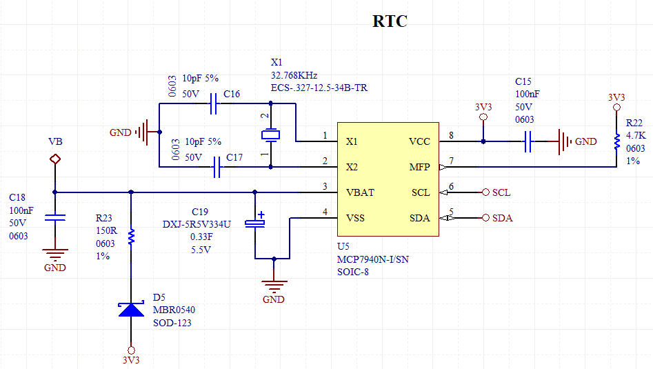
This is my current RTC circuit...

enter image description here

Supercapacitor = DXJ-5R5V334U (ELNA)... DXJ-5R5V334U = 0.33F, 5.5V, ESR = 150 Ohms Resistor = 150 ohms 0603 100mW 1%

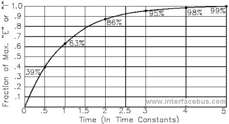
If I consider only the resistor, I have a RC constant of 0.33 * 150 = 49.5 (~50) seconds... 50 seconds x 3 = 150 seconds (3x RC = capacitor very well charged, 95%...). That is 150 seconds... divided by 60 = 2,5 minutes...

enter image description here

But if I consider also the ESR of the supercapacitor, I will have 300 Ohms in total, so that the charging time would be 5 minutes, double the time...

What value of resistance should I consider in practice? 150 ohms (2.5 minutes)? Or 300 ohms (5 minutes)?

Another question related to that, is: the VBAT pin consumption is 1.2uA (@ 3.3V)... If the supercapacitor is fully charged (like 95%) and the circuit loss the power supply of 3.3V (shutdown/off), the RTC will continue to operate from the VBAT pin (supercapacitor), so how much time the RTC would stay working from VBAT? (1 month? more?). As I said, consumption is 1.2uA (@ 3.3V) and the capacitor is 0.33F charged with something like 3 to 3.1V, how much time the RTC IC would stay working if the 3.3V rail keeps off "foreve"r? According the the datasheet of RTC chip, the "Backup supply voltage" minimum voltage is 1.3V. Do you know some online calculator where I could estimate that time of operating from VBAT pin after power-off of the board and capacitor being 95% charged? Could you calculate these things to me please? Or maybe an online calculator would be great also...

Thanks and Best Regards...

\$\endgroup\$
0

2 Answers 2

1
\$\begingroup\$

I use this website all the time to quickly calculate exactly what you're asking. https://sparks.gogo.co.nz/capacitor-formulae.html

\$\endgroup\$
4
  • \$\begingroup\$ Should I consider 150 ohms or 300 ohms? that's the main doubt... \$\endgroup\$
    – abomin3v3l
    Commented Oct 15, 2020 at 16:02
  • 1
    \$\begingroup\$ 150 ohms should be fine for just about any regulator. When the capacitor is at 0v, you will have an initial current of 22mA. That will continue to decrease the more the capacitor is charged. I would figure out how much current your regulator is able to handle. If its able to handle 1A, I'd use a 10ohm resistor which will give you a max current of 330mA and will charge the capacitor in about 10 seconds. With a 47ohm your max initial draw will be 70mA and charge time will be 46 seconds. \$\endgroup\$ Commented Oct 15, 2020 at 19:06
  • \$\begingroup\$ thanks mate. My doubt is if the ESR of the supercap should be considered or not to calculate the charge current... for example, it has 150 ohms of ESR, so it would be not needed to add any extra resistor in series like my schematic shows, because that 150 ohms of ESR of the supercap it would limit the current in 22mA just by its ESR... Got? \$\endgroup\$
    – abomin3v3l
    Commented Oct 15, 2020 at 20:09
  • 1
    \$\begingroup\$ That is correct. Thats a pretty high ESR though. \$\endgroup\$ Commented Oct 15, 2020 at 20:32
2
\$\begingroup\$

What value of resistance should I consider in practice? 150 ohms (2.5 minutes)? Or 300 ohms (5 minutes)?

The ESR of the cap plus external resistance. You should model the cap as a "pure" capacitance with a 150\$\Omega\$ resistor in series.

Do you know some online calculator where I could estimate that time of operating from VBAT pin after power-off of the board and capacitor being 95% charged?

Well this is on line, presumably you have a calculator, so bear with me a moment...

The Math

\$V_{cap} = \frac{q_c}{C}\$, where \$q\$ is the charge on the cap in coulombs, and \$C\$ is the capacitance. And \$q_c(t) = \int i_c dt\$. It's probably safe to assume that the RTC clock current consumption is constant or goes down as voltage goes down, but your should check this. If true, then the change in charge is just equal to current times time: \$\Delta q_c = \Delta i_c t\$. Then \$\Delta V_c = \frac{\Delta q_c}{C} = \frac{i_c \Delta t}{C}\$.

If you want to go from 3.1V down to 1.3V, then \$\Delta V_c = \mathrm{3.1V - 1.3V = 1.8V}\$. Then doing a bit of algebra gets \$\Delta t = \frac{C \Delta V_c}{i_c}\$. Using your numbers, \$\Delta t\$ is then \$\mathrm{\frac{1.8V\ 0.33F}{1.2\mu A} = 495 \cdot 10^3}\$ seconds.

However -- Shotkey diodes leak, particularly at high temperatures. You may want to revisit your diode choice.

\$\endgroup\$

Your Answer

By clicking “Post Your Answer”, you agree to our terms of service and acknowledge you have read our privacy policy.

Not the answer you're looking for? Browse other questions tagged or ask your own question.