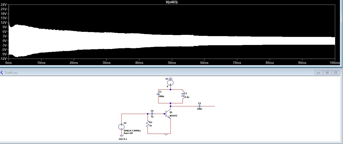
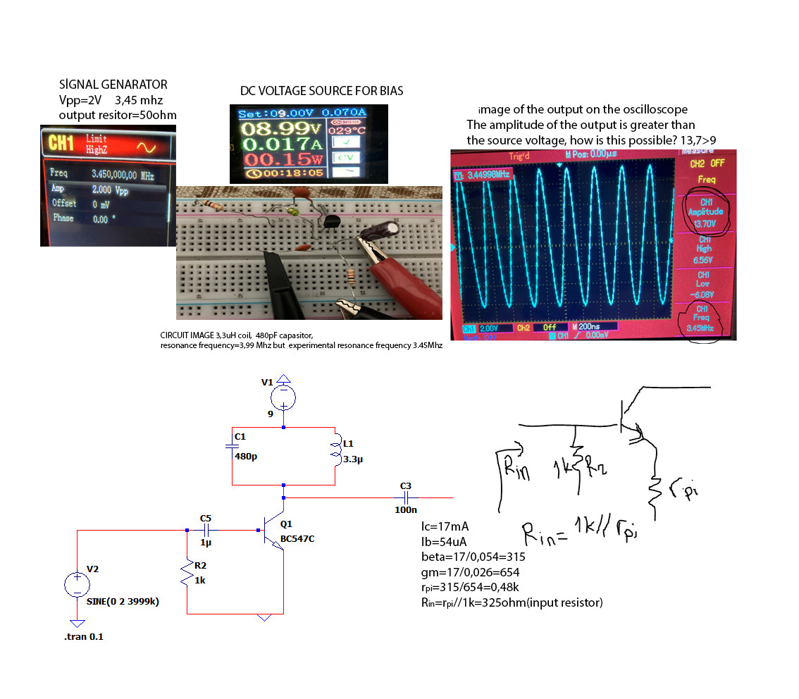
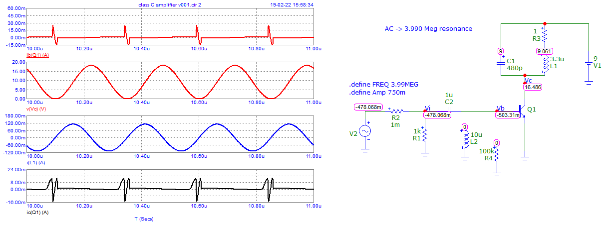
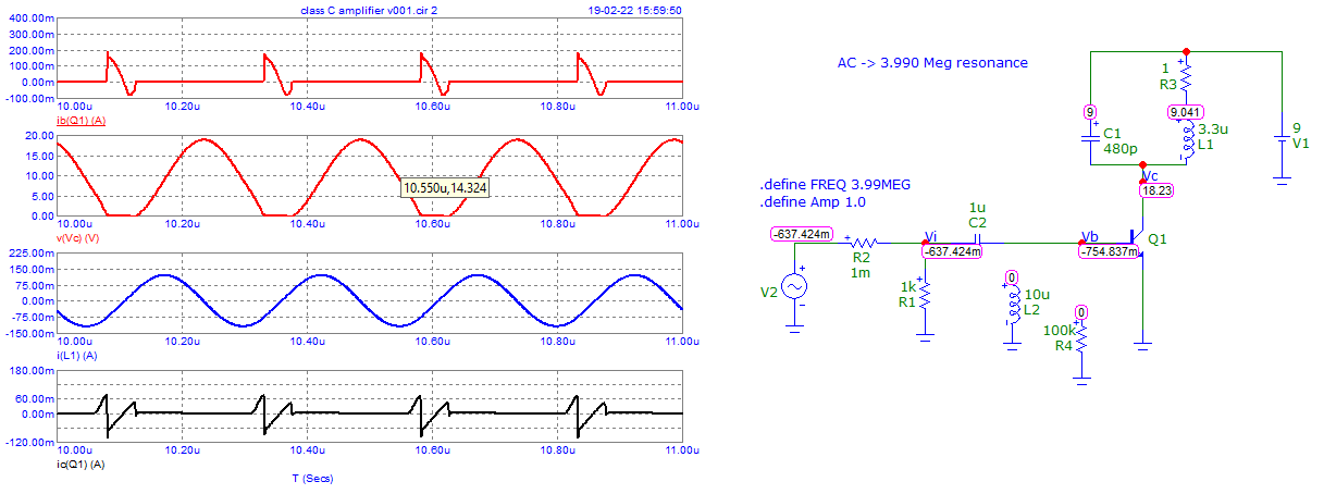
I designed a class C amplifier. I used a signal generator for the input signal. For the resonance circuit, I used a 3.3uH coil and a 480pF capacitor. The transistor is BC547-C.
The resonance frequency for these values is 3.99 MHz. Due to the tolerance values of the circuit elements and the use of breadboard, the maximum output amplitude was realized at 3.45MHz. This is an expected situation.
There are three questions that bother me.
How did the amplitude of the output become greater than the source voltage? As you increase the coil value (for example 10mH,) the amplitude of the output becomes larger at the resonant frequency.
The output resistance of the signal generator is 50 ohms. Impedance matching is essential for maximum power transfer. For this, I calculated the input resistance of the transistor. If I'm not wrong, I calculated the Rpi resistor as 480ohm. The calculation is available in the picture. I wanted to select the base resistance small to bring the input resistance closer to 50 ohms. I tried values like 100ohm, 330ohm, etc. However, the maximum output amplitude was achieved when the base resistance was 1k. Why did the maximum amplitude occur with thr 1k value?
If the amplitude of the input signal is less than 0.7 volts, this circuit would not work because the transistor needs about 0.7V for the base to be triggered or to conduct. How can this problem be solved when the signal amplitude is below 0.7 volts? How can the circuit be operated?
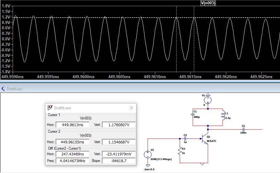
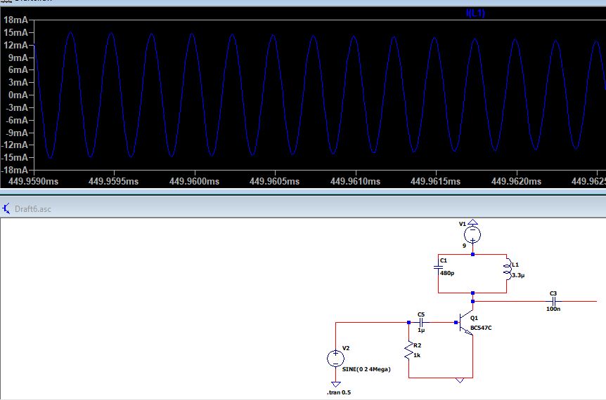
edit:LTSpice simulation image.very different with results from real experiment.
