1
\$\begingroup\$

I have a lovely pair of speakers that achieve their almost flat response by dampening spikes. Consequently they eat amp power for breakfast. I have been given a 400W RMS per channel 19" rack mount MOSFET PA amp from the 1980s.

It definitely takes pro line level input of some type as it's whisper quiet when driven from a normal consumer level line out.

The PA amp's inputs are via 1/4" mono jacks. The case contains two completely separate amps, they even have their own transformers & power supplies.

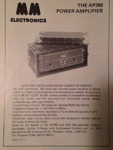
The amp was made by a small unknown UK company long before pdf datasheets. This is all I can find. It's exactly the same apart from output power, mine is 400WPC and this one is 200WPC. And mine is a bare 19" case.

enter image description here

Since definitions of pro line level have morphed over the decades and this case is complicated by not involving 'proper' balanced inputs I'm rather stumped by what to do.

Has anyone out there faced this situation before?

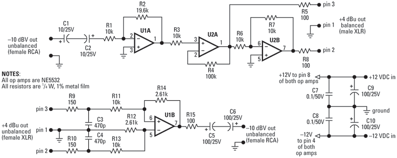
I'm reasonably competent with electronics so my immediate thought was to knock up an opamp circuit like this one:

enter image description here

From here: https://www.emusician.com/gear/build-the-em-104-level-converter

Although I'm not bad at electronics my main focus is industrial control systems and embedded stuff. Mostly digital; the majority of analogue stuff I have to face is mostly PSUs and pre ADC grooming of unipolar DC signals.

Am I right in thinking that if I use that circuit and only use the non-inverted output + Gnd to drive the amp I'll only get half the signal amplitude?

I'm quite reluctant to just replace the opamp's gain resistor with a trimmer and Rambo it because my speakers have Decca ribbon tweeters and other nice things in them that are not known for dealing well with clipping etc.

There are too many unknowns involved so before I do anything irreversible I thought I'd ask for advice. Thanks for any that you might have.

\$\endgroup\$
4
  • \$\begingroup\$ yes it is probably +4dBu in balanced. What you have looks good, but you have only 12dB of gain - 6dB on the input buffer and another 6 when you balance at unit gain. Personally I would make the input a "swinging gain stage" with a dual 10k lin pot, or at least have some jumpers to set the gain in steps of say 3dB. By the way R4 and R3 are superfluous but you probably want a DC block cap (10u electrolytic) and a 10k resistor to GND on pin 3 U2A - U1A may have DC offsets. R5 and 8 are a bit bit, I would go with 47R. \$\endgroup\$
    – danmcb
    Commented Mar 24, 2022 at 8:18
  • \$\begingroup\$ usual way to do switched gain is make R2 higher (for max gain) and then have jumpers to decrease it with various values, to get gain steps. \$\endgroup\$
    – danmcb
    Commented Mar 24, 2022 at 8:19
  • \$\begingroup\$ I don't find a link for swinging gain stage, don't have time to draw one. Take a 10k pot, put it in an inverting op amp, wiper goes to the - input, put (say) a 4k7 resistor from one end to the output, the input goes to the other end via another 4k&. Now you have a stage with a gain continuously variable from 1/3 to 3. \$\endgroup\$
    – danmcb
    Commented Mar 24, 2022 at 8:23
  • 1
    \$\begingroup\$ You need to know the input impedance. Having a modern preamp may not drive the input if it is 600 ohms for example, as modern inputs have much higher impedance. \$\endgroup\$
    – Justme
    Commented Mar 24, 2022 at 9:09

1 Answer 1

1
\$\begingroup\$

So it sounds like you just need a stereo +15dBV pre amp. If you search 'Stereo LINE PRE-Amplifier, 15DB, 12VDC' you find a pre built box that will do this for you. or... you can go the audiophile route where you can spend +$10k on just the pre-amp... but they promise you have angels dancing in your head ;-) In regards to your circuit, you want a gain of (10^(15/20)) = 5.6 times.

  • U1A has a gain of (19.6/10)= 1.96
  • U2A is just a buffer
  • U3A is a unity gain inverter and the differential output multiplies the gain x2, thus about x4, still not quite 5.6

If you want to roll your own, increase R2 to 56k, change U2A to non inverting and tap your output from U2A via a 100R resistor. U2B not required. Make sure you use an audio grade op-amp with a gain bandwidth of 500kHz.

\$\endgroup\$

Your Answer

By clicking “Post Your Answer”, you agree to our terms of service and acknowledge you have read our privacy policy.

Not the answer you're looking for? Browse other questions tagged or ask your own question.