1
\$\begingroup\$

I posted earlier about using BUZ11 Mosfets in my project and driving them with a CA3081 NPN transistor array. But as I need 24 Mosfets, the circuit parts count is still too high.

I have researched several other Mosfets, looking for one that is 3.3v compatible and capable of 6A output with out getting too hot and, can be driven directly from both an ESP32 and a PCF8575 IO port Expander board.

I found the IRLR7843 that seems like it should work.

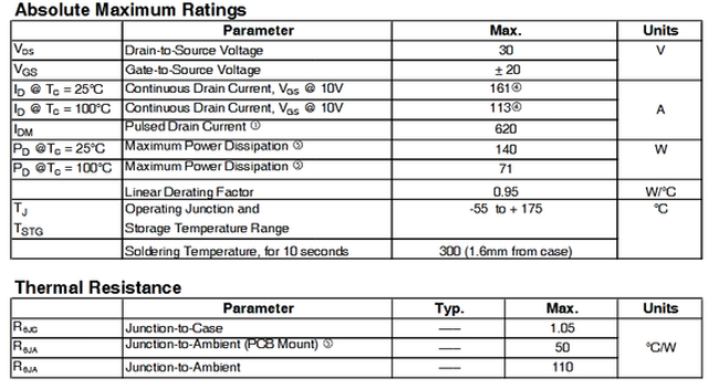
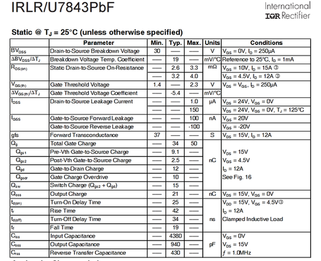
The data sheet shows a Max Gate Threshold Voltage of 2.3v, with a very low Static Drain-to-Source On-Resistance of 3m ohm @ VGS = 10V, ID = 15A and VGS = 4.5V, ID = 12A

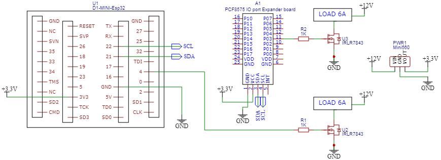
I am new to using Mosfets and not sure if my reasoning is correct, any help would be greatly appreciated, thanks. Here is my circuit idea:

enter image description here

Here is the data sheet for the IRLR7843:

enter image description here enter image description here

enter image description here

\$\endgroup\$

1 Answer 1

1
\$\begingroup\$

Gate threshold is irrelevant when using a MOSFET as a switch. That's the voltage it just barely starts to conduct. It is only useful for analog applications. You want the Vgs were the MOSFET actually conducts well which is the Vgs given for the rated to achieve the rated RDson.

So for this MOSFET you want a Vgs of at least 4.5V since that is the lowest voltage to achieve one of the rated RDson. Therefore this MOSFET is not considered to be 3.3V compatible.

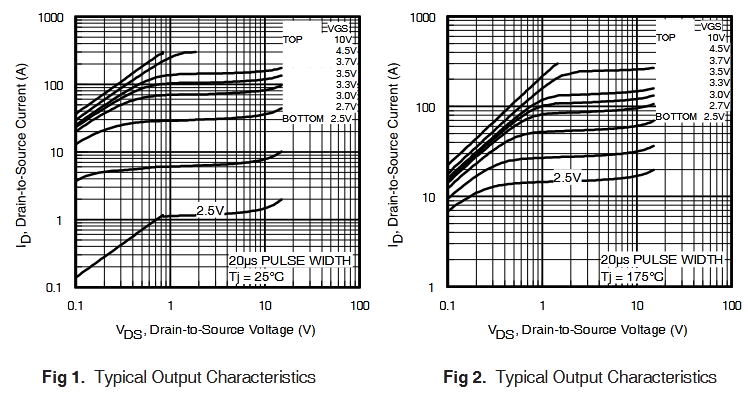
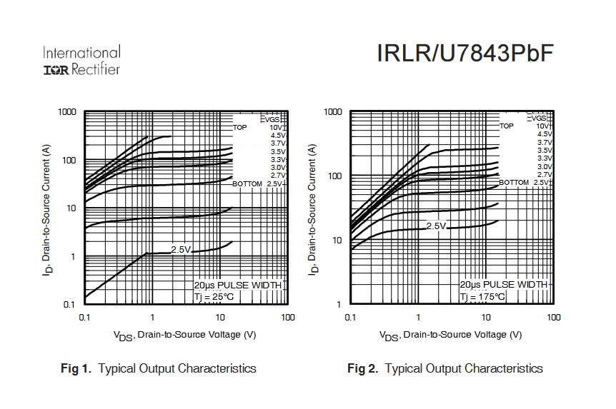
It might still work in your application if your current is low and in this case you look to the Id vs Vgs curve to find out what the actual RDson will be for your applied gate voltage:
enter image description here

For the 25C graph, it cuts at the low end so we can't see what it is at Id = 6A. But you can see that for Vgs = 3.3V, Vds = 0.1V when Id = 10A. So that is an RDson = Vd/Id = 9mOhm.

MOSFET source-drain resistance changes with temperature, often heating up, so there is also a graph for 175C. Again, we see that for Vgs = 3.3V, Vds = 0.1V when Id = 15A. Therefore RDson = 7mOhm.

So as far as that is concerned your MOSFETs are quite oversized for the current so you will get away with 6A if you use a Vgs below that required for the specified RDson.

Technically you would calculate the dissipated power using the current and RDson and use the thermal resistance of the MOSFET package to ambient to calculate the temperature to see if it is reasonable. But the current and resistance are so low and the package is so huge I already know it won't overheat.


Second consideration is gate drive current. The value for this is the total gate charge of the MOSFET. But I won't go into how to use it here. Every switch transition causes the MOSFET to heat up. If you switch infrequently it won't matter. If you switch frequently like with PWM then you need to be able to provide high current pulses so the MOSFET quickly transitions when rising and falling to minimize this heat.

If you plan on switching the MOSFET at high frequency this port expander cannot provide sufficiently high current pulses to minimize heating due to switching. You would need a real gate driver.

I do NOT recommend the 1K gate drive resistor lest you slow down the switching so much it overheats from a single transition. Your port expander already has excessive output impedance and low current drive capability. You don't need to slow it even more with a gate resistor. You normally use one to control ringing from fast switching and this will not be fast. This is not a BJT where you need to limit base current with a resistor.

\$\endgroup\$
15
  • 1
    \$\begingroup\$ If you are using the port expander at 3.3V it will not achieve a good RDson. Whether the RDson is workable in your specific application can be determined by examining the Id vs Vgs curve of the graph in order to calculate the RDson when you apply 3.3V to the gate. \$\endgroup\$
    – DKNguyen
    Commented Feb 13, 2023 at 4:46
  • 1
    \$\begingroup\$ If infrequenct switching you typically do not need a driver unless the heating during transition is so large that even a single switching would overheat the transistor (either because the currents and voltages being switched are high or the gate drive current is far too low causing slow switching). \$\endgroup\$
    – DKNguyen
    Commented Feb 13, 2023 at 4:46
  • 1
    \$\begingroup\$ No, MOSFETS are a capacitor between gate-source. BJTs are a diode between base-emitter. That's the difference. When shutting off the port expander will go LO and drain the capacitor. Unless you are referring the current pulse through the drain-gate parasitic capacitance but that current pulse is not a problem until it is a problem. \$\endgroup\$
    – DKNguyen
    Commented Feb 13, 2023 at 5:19
  • 1
    \$\begingroup\$ Worth noting that the absolute maximum in/out current limit per IO on the PCF8575 is 20mA, so a small gate resistor should really be added since you're driving around 4nF of input capacitance on the gate, and without a resistor you will transiently exceed the max IO current rating during switching. Technically you need 250Ω to never exceed the maximum current rating, but since it's an extremely short transient and the latchup limit is 100mA you could go down as low as 50Ω. I'd go with 75Ω or 100Ω personally, unless you need to switch quickly, at which point I'd use a gate driver IC. \$\endgroup\$
    – Polynomial
    Commented Feb 13, 2023 at 7:30
  • 1
    \$\begingroup\$ I wrote a fairly in-depth answer about driving MOSFETs for PWM recently, which might be of interest if you are planning on doing any fast switching or PWM driving. \$\endgroup\$
    – Polynomial
    Commented Feb 13, 2023 at 7:31

Your Answer

By clicking “Post Your Answer”, you agree to our terms of service and acknowledge you have read our privacy policy.

Not the answer you're looking for? Browse other questions tagged or ask your own question.