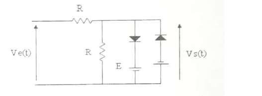
Im confused on how to treat this circuit the problem asked to graphically plot the voltage V_s = f(V_e), but i stumbled on the case where both the diodes are conducting -assuming they are ideal diodes- V_s = E and V_s = -E because they are parallel, but this is absurd right?
\$\begingroup\$
\$\endgroup\$
12
-
\$\begingroup\$ If V_s = E the diode is going to start to conduct, it's current, and that through R/2, is still zero. Therefore Ve(t) = 2 V_s = 2 E. The same goes for the opposite polarity. \$\endgroup\$– HarryHCommented Jun 4, 2023 at 12:03
-
\$\begingroup\$ I understand that the voltage of R/2 is non-zero because there is a current going thru it because the left diode is conducting, but i dont see why Ve(t) = 2V_s? @HarryH \$\endgroup\$– HellBoyCommented Jun 4, 2023 at 12:09
-
\$\begingroup\$ Oh wait are you saying that V_s(t) = E = Ve(t)/2? due to them being parallel branches? \$\endgroup\$– HellBoyCommented Jun 4, 2023 at 12:10
-
1\$\begingroup\$ responding to your last comment, no i get it when both the diodes arent conducting we study the voltage divider because its the only active circuit that is also parallel to V_s \$\endgroup\$– HellBoyCommented Jun 4, 2023 at 12:26
-
1\$\begingroup\$ Vs(t) = -E = Ve(t)/2 is where the right diode starts conducting. If Ve(t) goes further negative (it's the independent variable here) Vs(t) will stay at -E. \$\endgroup\$– HarryHCommented Jun 4, 2023 at 12:29
|
Show 7 more comments
1 Answer
\$\begingroup\$
\$\endgroup\$
15
this is absurd right?
Yes, it's absurd.
There is no situation when both diodes (assumed ideal) conduct at the same time: -
- \$D_{LEFT}\$ conducts when \$V_e\$ is positive and more than twice \$E\$ in magnitude
- \$D_{RIGHT}\$ conducts when \$V_e\$ is negative and more than twice \$E\$ in magnitude
-
\$\begingroup\$ how did you know the condition when each diode is conducting in relation to V_e and E? \$\endgroup\$– HellBoyCommented Jun 4, 2023 at 10:34
-
\$\begingroup\$ I looked at the circuit and considered it @HellBoy \$\endgroup\$– Andy akaCommented Jun 4, 2023 at 10:36
-
\$\begingroup\$ I did too but unfortunately i didnt get any idea, so what i did is consider the 4 cases first case which was absurd i had V_s = E- V_d and for the right diode, V_s = -E + V_d, which triggered the absurdity, second case D_left is conducting so V_s = E and V_e = ? idk how to use the basic laws to derive it because im confused by the parallel resistance which reside to the left to that diode. \$\endgroup\$– HellBoyCommented Jun 4, 2023 at 10:39
-
\$\begingroup\$ @HellBoy use Thevenin's theorem to convert Ve and the two resistors to a single voltage source (Ve/2) and one series resistor. That gets rid of the parallel resistor and un-confuses you. \$\endgroup\$– Andy akaCommented Jun 4, 2023 at 10:45
-
1\$\begingroup\$ I've rolled-back your question to its original form @HellBoy \$\endgroup\$– Andy akaCommented Jun 4, 2023 at 12:17

