I have little bit problem to transmit and receive data with nrf24l01. I use spi communication to communicate my MCU and nrf24l01. My spi communication is working. But i cannot receive any data from nrf24l01.
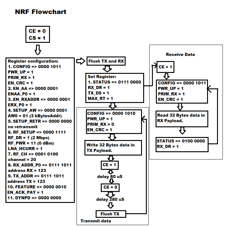
This is my configuration to drive nrf24l01:
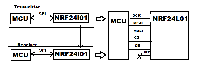
My Hardware configuration:
CE is pin in my nrf24l01. nrf24l01 has IRQ pin, but i don't use it. I make CS pin LOW if i want to access data from MCU to nrf24l01 and make it HIGH again when communication is finished.
This is my code to access spi from MCU to nrf24l01:
#define CS_HI           GPIO_SetBits(SPI_CS, CSN)
#define CS_LO           GPIO_ResetBits(SPI_CS, CSN)

unsigned short SendSPI(unsigned short val)
{
 SPI_I2S_SendData(SPI2, val);
 while(SPI_I2S_GetITStatus(SPI2, SPI_I2S_FLAG_TXE)==SET);
 SPI_I2S_ClearFlag(SPI2, SPI_I2S_FLAG_TXE);

 return(SPI_I2S_ReceiveData(SPI2));
}

void AccessSPI(unsigned char Cmd, unsigned char *pStatus, unsigned char *ptrBuff, unsigned char Total, unsigned char Operation)
{
 unsigned char m, temp;

 temp=Cmd;
 CS_LO;

 *pStatus=SendSPI(temp);        // Send Command
 if (Operation==kWriteSPI)
    {
     for (m=0; m<Total; m++)
        {
         temp=*ptrBuff;
         SendSPI(temp);
         ptrBuff++;
        }
    }
 else
    {
     for (m=0; m<Total; m++)
        {
         temp=SendSPI(0);
         // ptrbuff = &var (ptrbuff has address of value)
         *ptrBuff=temp; // store value from temp to ptrbuff value
         ptrBuff++; // increase address of ptrbuff
        }
    }
 CS_HI;
 }
Perhaps, this one can more help to understand my problem. This is my example code to make nrf24l01 configuration:
#define CE1_HI          GPIO_SetBits(PeriphSCE, SCE)
#define CE1_LO          GPIO_ResetBits(PeriphSCE, SCE)

void InitNRF24L01(void)
{
 unsigned char statusNRF,cmd;

 RFChan=20;
 Addr[0]=123;
 Addr[1]=0;
 Addr[2]=0;
 Addr[3]=0;
 Addr[4]=0;

 CE1_LO;
 CS_HI;
 //SCK_LO;
 //MOSI_LO;

 // Power Up
 Delay(100);
 cmd=(1<<PWR_UP)|(1<<PRIM_RX)|(1<<EN_CRC);
 AccessSPI(W_REGISTER|CONFIG, &statusNRF, &cmd, 1 , kWriteSPI);
 Delay(100);

 // Enable Auto Ack
 cmd=(1<<ENAA_P0);  //|(1<<ENAA_P1)|(1<<ENAA_P2)|(1<<ENAA_P3)|(1<<ENAA_P4)|(1<<ENAA_P5);
 AccessSPI(W_REGISTER|EN_AA, &statusNRF, &cmd, 1 , kWriteSPI);

 // Enable Data Pipe
 cmd=(1<<ERX_P0);   //|(1<<ERX_P1)|(1<<ERX_P2)|(1<<ERX_P3)|(1<<ERX_P4)|(1<<ERX_P5);
 AccessSPI(W_REGISTER|EN_RXADDR, &statusNRF, &cmd, 1 , kWriteSPI);

 // 3 bytes width
 cmd=(k3BytesAddr<<AW0);
 AccessSPI(W_REGISTER|SETUP_AW, &statusNRF, &cmd, 1 , kWriteSPI);

 // Retransmit
 cmd=0;     //(15<<ARC)|(0<<ARD);
 AccessSPI(W_REGISTER|SETUP_RETR, &statusNRF, &cmd, 1 , kWriteSPI);

 // 2 MBps-0dB-LNA On
 cmd=(k0dBm<<RF_PWR)|(kLNAGain<<LNA_HCURR)|(kRate2Mbps<<RF_DR);
 AccessSPI(W_REGISTER|RF_SETUP, &statusNRF, &cmd, 1 , kWriteSPI);

 // RF Channel
 cmd=RFChan;
 AccessSPI(W_REGISTER|RF_CH, &statusNRF, &cmd, 1 , kWriteSPI);

 // Set RX Address
  AccessSPI(W_REGISTER|RX_ADDR_P0, &statusNRF, &Addr[0], 5 , kWriteSPI);
  // Set TX Address
  AccessSPI(W_REGISTER|TX_ADDR, &statusNRF, &Addr[0], 5 , kWriteSPI);

  cmd=32;                                                                           // Total Payload 0 32 bytes
  AccessSPI(W_REGISTER|RX_PW_P0, &statusNRF, &cmd, 1 , kWriteSPI);

  cmd=(1<<EN_ACK_PAY);
  AccessSPI(W_REGISTER|FEATURE, &statusNRF, &cmd, 1 , kWriteSPI);
  cmd=0;
  AccessSPI(W_REGISTER|DYNPD, &statusNRF, &cmd, 1 , kWriteSPI);

  FlushTXFIFO();
  FlushRXFIFO();
  cmd=(1<<RX_DR)|(1<<TX_DS)|(1<<MAX_RT);                                                // Clear all status latched
  AccessSPI(W_REGISTER|STATUS, &statusNRF, &cmd, 1 , kWriteSPI);
}

void EnableReceive(void)
{
    unsigned char statusNRF, cmd;

    CE1_HI;
    cmd=(1<<RX_DR);
    AccessSPI(W_REGISTER|STATUS, &statusNRF, &cmd, 1 , kWriteSPI);
}

enum eStatus ReceiveData2(void)
{
    unsigned char statusNRF, addr, temp, cmd, output[32];
    unsigned char *pdat;

    //AccessSPI(R_REGISTER|STATUS, &temp, &statusNRF, 1, kReadSPI);

    temp=(1<<PWR_UP)|(1<<PRIM_RX)|(1<<EN_CRC);
    AccessSPI(W_REGISTER|CONFIG, &statusNRF, &temp, 1 , kWriteSPI);

    AccessSPI(R_REGISTER|FIFO_STATUS, &temp, &statusNRF, 1, kReadSPI);
    if ((statusNRF & (1<<RX_EMPTY))==0)
    {
         AccessSPI(R_REGISTER|STATUS, &temp, &statusNRF, 1, kReadSPI);
         addr=(statusNRF >> 1) & 0x07;
         if (addr<6)
         {
             pdat=output;
             AccessSPI(R_RX_PAYLOAD, &temp, pdat, 32, kReadSPI);
              /*int i;
              for(i=0; i<32; i++)
              {
                  USART_SendData(USART2, output[i]);
                  Delay(1);
              }*/

              FlushRXFIFO();
              return(kDataExist);
         }
         cmd=(1<<RX_DR);
         AccessSPI(W_REGISTER|STATUS, &statusNRF, &cmd, 1 , kWriteSPI);
         return(kNoData);
    }
    return(kNoData);
}

void FlushTXFIFO(void)
{
    unsigned char statusNRF, cmd;

    AccessSPI(FLUSH_TX, &statusNRF, &cmd, 0 , kWriteSPI);
}

void FlushRXFIFO(void)
{
    unsigned char statusNRF, cmd;

    AccessSPI(FLUSH_RX, &statusNRF, &cmd, 0 , kWriteSPI);
}

void Delay(unsigned int val)
{
 unsigned int m, n;

 for (m=0; m<val; m++)
    {
     for (n=0; n<1000; n++);
    }
}

void DelayuS(unsigned int val)
{
 unsigned int   m, i;

 for (m=0; m<val; m++)
 for (i=0; i<4; i++);
}

void SendData2(unsigned char *pDat)
{
    unsigned char statusNRF, cmd;

    cmd=(1<<PWR_UP)|(1<<EN_CRC);
    AccessSPI(W_REGISTER|CONFIG, &statusNRF, &cmd, 1 , kWriteSPI);
    AccessSPI(W_TX_PAYLOAD, &statusNRF, pDat, 32 , kWriteSPI);
    CE1_HI;
    DelayuS(kWaitBurst); // wait 80uS, i have checked in oscilloscope
    CE1_LO;
    DelayuS(280); // wait 280uS
    FlushTXFIFO();
}
and this is my main program:
unsigned char dataNRF[32] = {1, 2, 3, 4, 5, 6, 7, 8, 9, 10,
                        11, 12, 13, 14, 15, 16, 17, 18, 19, 20,
                        21, 22, 23, 24, 25, 26, 27, 28, 29, 30,
                        31, 32};
int main(void)
{
    // nyalakan NRF24l01
    InitSPI();
    InitNRF24L01();
#if defined(receiver)
    EnableReceive();
#endif

    while(1)
    {
#if defined(receiver)
        ReceiveData2();
#elif defined(transmitter)
        unsigned char *temp = &(dataNRF[0]);
        SendData2(temp);
#endif
    }
}
I was think, my problem is in my configuration. I read again in my nrf24l01 datasheet, but i cannot solved it. I need some help to solved this. Thank you.
UPDATE 1: Perhaps, somebody can check my spi configuration. if i have something wrong with my code, i need some advice. I'm used STM32F103 as MCU. And this is my initialisation for my spi.
void InitSPI(void)
{
 SPI_InitTypeDef SPI_InitStruct;
 GPIO_InitTypeDef GPIO_InitStructure;

 RCC_APB2PeriphClockCmd(RCC_APB2Periph_AFIO, ENABLE);
#if defined(minsys)
 RCC_APB1PeriphClockCmd(RCC_APB1Periph_SPI2, ENABLE);
 RCC_APB2PeriphClockCmd(RCC_APB2Periph_GPIOB | RCC_APB2Periph_GPIOC, ENABLE);
#elif defined(audio)
 GPIO_PinRemapConfig(GPIO_Remap_SWJ_JTAGDisable, ENABLE);
 GPIO_PinRemapConfig(GPIO_Remap_SPI1, ENABLE);
 RCC_APB2PeriphClockCmd(RCC_APB2Periph_SPI1|RCC_APB2Periph_GPIOA|RCC_APB2Periph_GPIOB, ENABLE);
 GPIO_PinRemapConfig(GPIO_Remap_FSMC_NADV, DISABLE);
#endif

 GPIO_InitStructure.GPIO_Pin = SCLK|MOSI;
 GPIO_InitStructure.GPIO_Mode = GPIO_Mode_AF_PP;
 GPIO_InitStructure.GPIO_Speed = GPIO_Speed_50MHz;
 GPIO_Init(SPI, &GPIO_InitStructure);

 GPIO_InitStructure.GPIO_Pin = CSN;
 GPIO_InitStructure.GPIO_Mode = GPIO_Mode_Out_PP;
 GPIO_InitStructure.GPIO_Speed = GPIO_Speed_50MHz;
 GPIO_Init(SPI_CS, &GPIO_InitStructure);

 GPIO_InitStructure.GPIO_Pin = MISO;
 GPIO_InitStructure.GPIO_Mode = GPIO_Mode_IPU;
 GPIO_InitStructure.GPIO_Speed = GPIO_Speed_50MHz;
 GPIO_Init(SPI, &GPIO_InitStructure);

 GPIO_InitStructure.GPIO_Pin = SCE;
 GPIO_InitStructure.GPIO_Mode = GPIO_Mode_Out_PP;
 GPIO_InitStructure.GPIO_Speed = GPIO_Speed_50MHz;
 GPIO_Init(PeriphSCE, &GPIO_InitStructure);

 SPI_InitStruct.SPI_BaudRatePrescaler=SPI_BaudRatePrescaler_16;
 SPI_InitStruct.SPI_CPHA=SPI_CPHA_1Edge;
 SPI_InitStruct.SPI_CPOL=SPI_CPOL_Low;
 SPI_InitStruct.SPI_DataSize=SPI_DataSize_8b;
 SPI_InitStruct.SPI_Direction=SPI_Direction_2Lines_FullDuplex;
 SPI_InitStruct.SPI_FirstBit=SPI_FirstBit_MSB;
 SPI_InitStruct.SPI_Mode=SPI_Mode_Master;
 SPI_InitStruct.SPI_NSS=SPI_NSS_Soft;

#if defined(minsys)
 SPI_Init(SPI2, &SPI_InitStruct);
 SPI_Cmd(SPI2, ENABLE);
#elif defined(audio)
 SPI_Init(SPI1, &SPI_InitStruct);
 SPI_Cmd(SPI1, ENABLE);
#endif
}
UPDATE 2: This is my simple code to read STATUS Register, it will return 0x00 right now. What procedure that i need to write or read register in nrf24l01?
CE1_LO;
CS_HI;
unsigned char temp, statusNRF;

// Power up
Delay(100); // 72 ms , checked in my oscilloscope
temp=(1<<PWR_UP)|(1<<PRIM_RX)|(1<<EN_CRC);
AccessSPI(W_REGISTER|CONFIG, &statusNRF, &temp, 1 , kWriteSPI);
Delay(100); // 72 ms , checked in my oscilloscope, more than enough

temp=(1<<RX_DR)|(1<<TX_DS)|(1<<MAX_RT);
AccessSPI(W_REGISTER|STATUS, &statusNRF, &temp, 1 , kWriteSPI);
AccessSPI(R_REGISTER|STATUS, &temp, &statusNRF, 1, kReadSPI);
USART_SendData(USART2, statusNRF); // I send to serial, and always read 0x00


