12
\$\begingroup\$

My biggest challenge with this question is its ridiculously steep roll-off rate.

I am assuming that the signal is undetectable if its gain is -20 dB. This means that, within the transition band of 200 Hz, the signal strength needs to drop by 20 dB.

If my calculations are correct, this filter requires a roll-off rate of 1200 dB/dec. That requires 60 poles, which is obviously not feasible.

I would like to use an analog active filter with minimal ripple in the pass band. A large phase shift is not too important.

One potential solution is to use a notch filter at 5.2 kHz. However, frequencies above the bandwidth of the notch filter are still not sufficiently filtered.

Please point out any flaws in my logic and or propose potential solutions. Thank you.

\$\endgroup\$
11
  • 16
    \$\begingroup\$ Calling -20dB undetectable is quite a stretch \$\endgroup\$
    – PlasmaHH
    Commented Mar 10, 2018 at 15:23
  • 1
    \$\begingroup\$ @WhatRoughBeast ??? I realize that he divided 4500 by 20 to get 225 poles; what I'm challenging is how he got the 4500 in the first place. \$\endgroup\$
    – Dave Tweed
    Commented Mar 10, 2018 at 16:44
  • 7
    \$\begingroup\$ What kind of answer are you expecting Tamir? Analog passive/active? Digital IIR/FIR? Wave digital filter? FFT + Remove unwanted stuff + IFFT? \$\endgroup\$ Commented Mar 10, 2018 at 16:48
  • 4
    \$\begingroup\$ How much passband ripple is acceptable? \$\endgroup\$ Commented Mar 10, 2018 at 17:28
  • 1
    \$\begingroup\$ "with minimal ripple in the pass band" - 'minimal' is not a specification. \$\endgroup\$ Commented Mar 11, 2018 at 14:48

6 Answers 6

21
\$\begingroup\$

You have assumed a 20dB/dec per filter order roll-off for your filter. This is not true for all filter types.

Let \$f_0 = 5 \mathrm{kHz}\$ and \$f_{\mathrm{stop}} = 5.2 \mathrm{kHz}\$. Then $$\frac{f_{\mathrm{stop}}}{f_0} = 1.04.$$

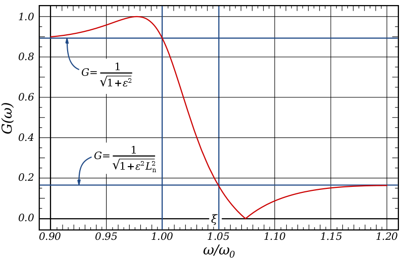
Have a look at this fourth order elliptic filter taken from the Wikipedia article. elliptic

Although it does not quite meet your requirements you can see it is feasible. A higher order elliptic filter can achieve what you are after.

You should keep in mind that elliptic filters can do disturbing things to the phase of the signal. Since you did not mention anything about your phase constraints, I have assumed that an elliptic filter is suitable.

\$\endgroup\$
3
  • \$\begingroup\$ That's not a bad idea. 6th order elliptic LPF has steep enough transition slope if 3dB passband ripple and max. -20dB leakage at 5200Hz and higher is allowed. The result was got with a filter calculator, I only inputted different orders and limits until a proper frequency response popped out. Sixth order means only three 2nd order blocks cascaded. No idea, will it be realizable in practice with usual component tolerances as an analog opamp filter. That needs more simulations. \$\endgroup\$
    – user136077
    Commented Mar 10, 2018 at 21:10
  • \$\begingroup\$ Hi and thanks for a nice answer. Just a curiosity, when I look at wikipedia the poles seem to lie on an ellipsis, is that where the name comes from or is it a coincidence? \$\endgroup\$ Commented Mar 11, 2018 at 11:55
  • 1
    \$\begingroup\$ @mathreadler I believe the name comes from the elliptic rational function that appears in the transfer function of the elliptic filter. The poles of the elliptic filters are a function of the Jacobi elliptic cosine function. Hence they lie on an ellipse. \$\endgroup\$
    – user110971
    Commented Mar 11, 2018 at 12:07
21
\$\begingroup\$

This kind of sharp rolloff requires a digital filter. Don't even think about analog. You need to convolve the input with a sinc function. The width of the sinc function (the number of kernel points) defines the stop band attenuation.

I haven't done the math, but some very quick (could be off, your job to do properly) calculations says you probably need a few 100 points if sampling at 20 kHz. 200 points at 20 kHz means a MAC rate of 4 MHz. That's doable, in fact well below what modern DSPs can do rather easily. That means your problem is quite tractable. Something like a E series dsPIC can do this, and that's rather low end if you're only looking for DSP capability.

\$\endgroup\$
3
  • 3
    \$\begingroup\$ this is actually a FIR filter. A fast simulation showed that 128 tap filter with rectangular windowing is enough. The coefficients are taken from the sinc impulse response of the ideal 5100Hz LPF. The first sidelobe is just -20dB at approx. 5250Hz (seen from a filter calculator) \$\endgroup\$
    – user136077
    Commented Mar 10, 2018 at 20:30
  • 2
    \$\begingroup\$ @user: OK, so that means it's actually a little easier than my rough estimate above. I'd probably make the kernel a little wider, just to have some margin, especially since that's still well within the capability of even a modest DSP. \$\endgroup\$ Commented Mar 10, 2018 at 21:25
  • \$\begingroup\$ There are some really good resources for the filter and which window function to use: I personally like dspguide.com \$\endgroup\$ Commented Mar 11, 2018 at 13:05
4
\$\begingroup\$

If you allow a substantial delay or process a recorded signal you can simply do FFT , remove unwanted components and invert the transform. You must truncate the fft with proper window function to keep the ringing acceptable.

\$\endgroup\$
1
  • 8
    \$\begingroup\$ I think for a transition band this narrow, you need to say a lot more about how to select the window function to make this answer useful for solving the problem. \$\endgroup\$
    – The Photon
    Commented Mar 10, 2018 at 15:43
4
\$\begingroup\$

I'd pick an audio codec chip (ADC+DAC), route the ADC digital output to the DAC input, and set the sample rate to 10kHz.

These chips already include the digital filter engine you need. A quick datasheet check seems to confirm you'll get the filter performance you need.

\$\endgroup\$
4
  • \$\begingroup\$ Are you sure about that? \$\endgroup\$ Commented Mar 11, 2018 at 22:57
  • \$\begingroup\$ Not 100% sure, but I don't see any reason it wouldn't work with a sigma delta codec, some can sample down to 8kHz... \$\endgroup\$
    – bobflux
    Commented Mar 11, 2018 at 23:23
  • \$\begingroup\$ But I mean why do you believe it will reject the unwanted frequencies, rather than aliasing them? \$\endgroup\$ Commented Mar 11, 2018 at 23:39
  • \$\begingroup\$ The usual audio ADC is a sigma delta with huge oversampling factor followed by sharp digital filter. Most of these will run from Fs=8k to 96-192k. Aliasing is avoided by a simple 1st order lowpass before the ADC, and oversampling takes care of it. They should work fine around Fs=10kHz with the right clock frequency. \$\endgroup\$
    – bobflux
    Commented Mar 12, 2018 at 1:04
4
\$\begingroup\$

You already have many nice answers with good traditional solutions, elliptic filters, (short time) FFT, etc., so I was thinking I can add something from the sub-band coding / wavelet transform world.

Sub-band coding means to subdivide the frequency spectrum into "bins", each of these bins has its own associated filter. The tighter bands, the broader filters in time domain (naturally) - but in areas where we don't need very tight bands we can get away with really short & cheap-to-calculate filters.

Wavelets are functions which are the result of a specific type of sub-band filters which are generated by iterated filtering followed by subsampling.

The idea would be to find the sub-bands of interest which would allow us to squeeze the computations the most, but still get good granularity at the band of interest.

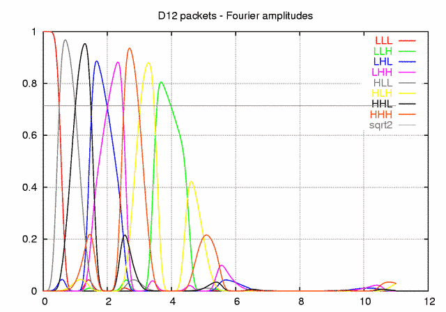
Example of a Daubechies 12 tap packet decomposition in three levels (Wikipedia):

Enter image description here

We can then selectively sum up these to get the response we want. And the ones which we don't want to add - we don't even have to compute! We will need slimmer ones closer to the 5-5.2 kHz band to be able to get steep enough behaviour. But on the other hand, far away from the 5-5.2 kHz band we can get away with only a few subdivisions.

\$\endgroup\$
2
  • \$\begingroup\$ This is more of an advert than an answer. \$\endgroup\$ Commented Mar 14, 2018 at 15:26
  • \$\begingroup\$ @HarrySvensson I can try to be more specific but I don't have as much free time these days as I used to have to improve on answers. \$\endgroup\$ Commented Mar 14, 2018 at 18:20
3
\$\begingroup\$

if you can GUARANTEE a sinusoidal input, then a one-shot monostable (74121) may suffice. Or the re-triggerable 122/123.

Use a comparator prior to the 74121/122/123

Some MCUs include analog comparators as their peripherals; once converted to square wave, you can use timers etc to detect above/below 5,000Hz, if the MCU has a XTAL-stabilized clock. No need for a temperature-sensitive monostable.

\$\endgroup\$
3
  • 3
    \$\begingroup\$ Interesting, but what makes you think the input might be sinusoidal? Seems pretty utopic to make that assumption without any particular reason. \$\endgroup\$ Commented Mar 10, 2018 at 22:25
  • 1
    \$\begingroup\$ i think by sating as the first 4 words of his answer "if you can GUARANTEE", then this is a novel solution. \$\endgroup\$ Commented Mar 12, 2018 at 3:08
  • \$\begingroup\$ I used this approach (the retriggerable 74123) to detect wheel lockup in an anti-skid-brake system; when the 74123 timed out, the hydraulic cylinder was driven from 2N3055 to pulse the brakes. We only got about 2 pulses per second, because of the hydraulic timeconstant. \$\endgroup\$ Commented Mar 17, 2018 at 4:24

Your Answer

By clicking “Post Your Answer”, you agree to our terms of service and acknowledge you have read our privacy policy.

Not the answer you're looking for? Browse other questions tagged or ask your own question.