2
\$\begingroup\$

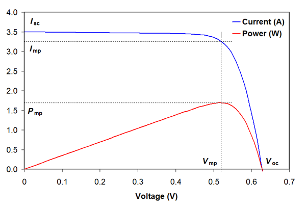
I am trying to design and build a MPPT charger to charge a battery from a solar cell. From what I understand, an MPPT controller is basically a buck converter where the output voltage is optimized such that the current being drawn from a solar cell is Imp, which will cause the voltage to be at Vmp.

IV curve of solar cell

Ideally, the current should be drawn constantly at Imp to maximize the power, but during the off stage of a buck converter, no current is being drawn from the solar cell when it could have been producing power. Is this really the case, and is there a way to store/use that power during the on stage? Would adding an inductor and capacitor (L2 and C2 as shown below) to the input of the buck converter effectively store the energy from the off stage of the buck converter such that it will be used during the on stage? Schematic showing how L2 and C2 are connected

\$\endgroup\$
1
  • \$\begingroup\$ If you make C2 large enough that its voltage varies minimally during the switching cycle then L2 is not essential and no energy is wasted. If there is noticeable ripple voltage on C2 then without L2 you get resistive losses due to charge and discharge of C2. \$\endgroup\$
    – Russell McMahon
    Commented Mar 27, 2019 at 14:31

2 Answers 2

0
\$\begingroup\$

Is this really the case [?]

Yes. Without \$L_2, C_2\$ there is no input current when the transistor is off and the solar cell doesn't deliver power other than for its own heating up.

...and is there a way to store/use that power during the on stage?

Yes, your \$C_2\$ can do that for you.
And if you're not concerned about EMC, your \$L_2\$ can be the parasitic inductance of the cables. What I mean to say is that \$L_2\$ isn't necessary for the functioning of the circuit.

Would adding an inductor and capacitor (L2 and C2 as shown below) to the input of the buck converter effectively store the energy from the off stage of the buck converter such that it will be used during the on stage?

Absolutely.
And if the switching period is short enough, but not too short, you can see a current and voltage ripple on the clamps of the solar panel, which enables you to track the Maximum Power Point (MPP). If the ripple is too large, i.e.: influencing the 'average MPP' too much, then your switching frequency is too low.

\$\endgroup\$
0
\$\begingroup\$

By off state, I'm assuming you mean the part of the cycle where the buck converter is not feeding current into the buck converter.

If you look at the circuit you've shown above, you see two similar sections on the input and output, formed by an inductor in series and a capacitor to ground. This is a low pass filter, which basically lets DC through, but the high frequency AC from the switching section is heavily attenuated. What this means is that while to the transistor in the middle, it looks like the load on the supply is a high frequency square(ish) wave, to the solar cell it looks like a steady load, with only a minor ripple. The same thing happens at the output, the load receives an almost constant current or voltage, while the middle of the circuit sees high frequency AC.

\$\endgroup\$
4
  • \$\begingroup\$ So if a were to use a traditional buck converter without the low pass filter on the input, would it be less than optimal for use with a solar cell since neither the high or low state of the load is at the maximum power point (it's somewhere in between)? \$\endgroup\$
    – user182015
    Commented Jun 12, 2018 at 0:42
  • \$\begingroup\$ Buck converters usually have at least a little smoothing on the input, otherwise they would radiate like crazy. It will probably work fine without a huge filter, but it wouldn't hurt to add an inductor between the panel and the power supply \$\endgroup\$
    – C_Elegans
    Commented Jun 12, 2018 at 0:51
  • \$\begingroup\$ @C_Elegans Under certain conditions it MIGHT hurt to put an inductor between the panel and the power supply, see the Middlebrook criterion: ethesis.nitrkl.ac.in/7104 \$\endgroup\$
    – John D
    Commented Jun 12, 2018 at 0:56
  • \$\begingroup\$ A 'traditional' buck converter tends to include the input capacitor, so it draws a steady current. The stray inductance of the input capacitor is a significant factor in the design of the overall buck. \$\endgroup\$
    – Neil_UK
    Commented Jun 12, 2018 at 5:36

Your Answer

By clicking “Post Your Answer”, you agree to our terms of service and acknowledge you have read our privacy policy.

Not the answer you're looking for? Browse other questions tagged or ask your own question.