12
\$\begingroup\$

I have a simple circuit that runs off of a 9V battery. I'm re-designing it so that it can also run off of an external 12V DC source (ie: a wall adapter). I want to design the circuit so that if both the battery and the wall adapter are connected simultaneously, the wall adapter is used, and the battery is effectively disconnected from the circuit.

I've found a few circuits online that might work, but they unfortunately might allow a trickle of current into the battery, and since it could be a non-rechargeable (ie: alkaline) cell, this could be disastrous.

I've considered the using a barrel jack with a normally-closed three-terminal contact configuration, but I'm not quite sure how to start. How would I go about designing such a circuit?

\$\endgroup\$
1
  • 2
    \$\begingroup\$ A trickle into Alkaline is usually OK. | If you do not mind slight loss a diode from battery to V+ means the diode will be reverse biased when adaptor is powered and battery will not be used. Ah yes - like your example link. Schottky allows slight reverse current - higher at high temp. Silicon diode has minimal reverse leakage. Either are unlikely to bother Alkaline cells. \$\endgroup\$
    – Russell McMahon
    Commented Sep 26, 2014 at 17:36

6 Answers 6

9
\$\begingroup\$

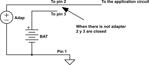
The NC (normally closed) terminals (2 & 3 in the sheet) must connect the battery. When you plug in the adapter, this terminals opens. Try to determine on which pin (in addition to pin 1) the adapter connects (i can't determine the number from the sheet).

Edit: The battery connects between pins 1 & 2.

schematic

simulate this circuit – Schematic created using CircuitLab

\$\endgroup\$
4
  • \$\begingroup\$ Should I also include the diodes mentioned in one of the other answers? Are they necessary, or do they protect from unexpected scenarios (ie: someone plugs in a 4V source instead of a 12V source). \$\endgroup\$
    – Cloud
    Commented Sep 26, 2014 at 17:52
  • \$\begingroup\$ The diodes are very inexpensive. It is an excellent proposal to add these two diodes. Improved design to a negligible cost. \$\endgroup\$ Commented Sep 26, 2014 at 17:58
  • \$\begingroup\$ @Dogbert Umm...I don't know why Martin suggests this. They are completely unnecessary if you use this solution since the adaptor is disconnected from the battery when connected. \$\endgroup\$
    – ACD
    Commented Sep 26, 2014 at 20:17
  • 6
    \$\begingroup\$ The diodes allow you to use an existing jack, but another thing the diodes will provide is reverse voltage protection if someone plugs the battery in wrong, or the wrong type of adaptor (center negative instead of center positive). Its worth the 20 cents. \$\endgroup\$
    – Passerby
    Commented Sep 26, 2014 at 21:30
19
\$\begingroup\$

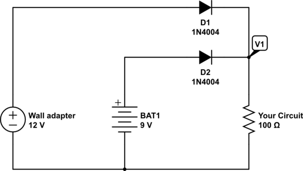
All you need is 2 diodes for your 2 power sources. Your circuit will use power from the one with the highest voltage.

schematic

simulate this circuit – Schematic created using CircuitLab

When the adapter is plugged in, V1 will be 11 volts (ish). When the adapter is removed, your circuit will have 8 volts at V1 from the battery. There is no risk of the battery being charged by the adapter as the battery diode will block all current in the reverse direction.

The diode part numbers are not critical. Just select diodes that match the current needed by your circuit.

\$\endgroup\$
9
  • 10
    \$\begingroup\$ Diode part numbers matter a little. You want schottky diodes, and they need to be able to handle the full current of the load. And the leakage of D2 can't be too high or the wall adaptor could dump charge to the battery. \$\endgroup\$
    – ACD
    Commented Sep 26, 2014 at 17:54
  • \$\begingroup\$ Regular silicon or germanium diodes work, no need for schottky. \$\endgroup\$
    – Passerby
    Commented Sep 26, 2014 at 22:12
  • \$\begingroup\$ I agreee with the schematic proposed by CarpetPython, however wouldn't the battery still provide forward bias current for D2 even when the wall adapter is connected ? Thus at V1, the voltage of both the battery and wall adapter are super imposed ? \$\endgroup\$
    – Luke Galea
    Commented Nov 23, 2015 at 22:42
  • \$\begingroup\$ @Luke Galea: The voltage of the wall adapter (12 V) is higher than the battery voltage (9 V), load current flows only through D1. The voltage V1 is higher than that of Bat1, the voltage over Diode D2 is oriented in reverse direction of D2. Only the very small leakage current is flowing through D2. There is no super imposing of both voltages, this would require a series connection of both voltage sources. \$\endgroup\$
    – Uwe
    Commented Jan 10, 2017 at 8:59
  • 1
    \$\begingroup\$ Why is D1 needed? \$\endgroup\$ Commented Jun 2, 2017 at 20:05
7
\$\begingroup\$

Take a look at the PowerPath Controller LTC4412 or the Prioritized PowerPath Controller LTC4417 from Linear Technology. They have some more of these PowerPath devices.

Or you can take a relay. The wall adapter controls the relay to open/close the line to the battery. AC wall adapter plugged in, relay on and battery line disconnected, vice versa. Then you have no voltage drop.

With the use of diodes, even shottky, you always have the disadvantage of the diodes voltage drop. And if the circuits current consumption is high, the size of the diodes will increase. The problem with voltage drop will get worse.

\$\endgroup\$
1
  • 1
    \$\begingroup\$ Considering op is modifying a 9v battery device, current draw isn't going to be huge anyway. A pair of germanium diodes will provide a minimal 0.3V draw at 1A or so, negligable honestly. \$\endgroup\$
    – Passerby
    Commented Sep 26, 2014 at 21:43
2
\$\begingroup\$

enter image description here

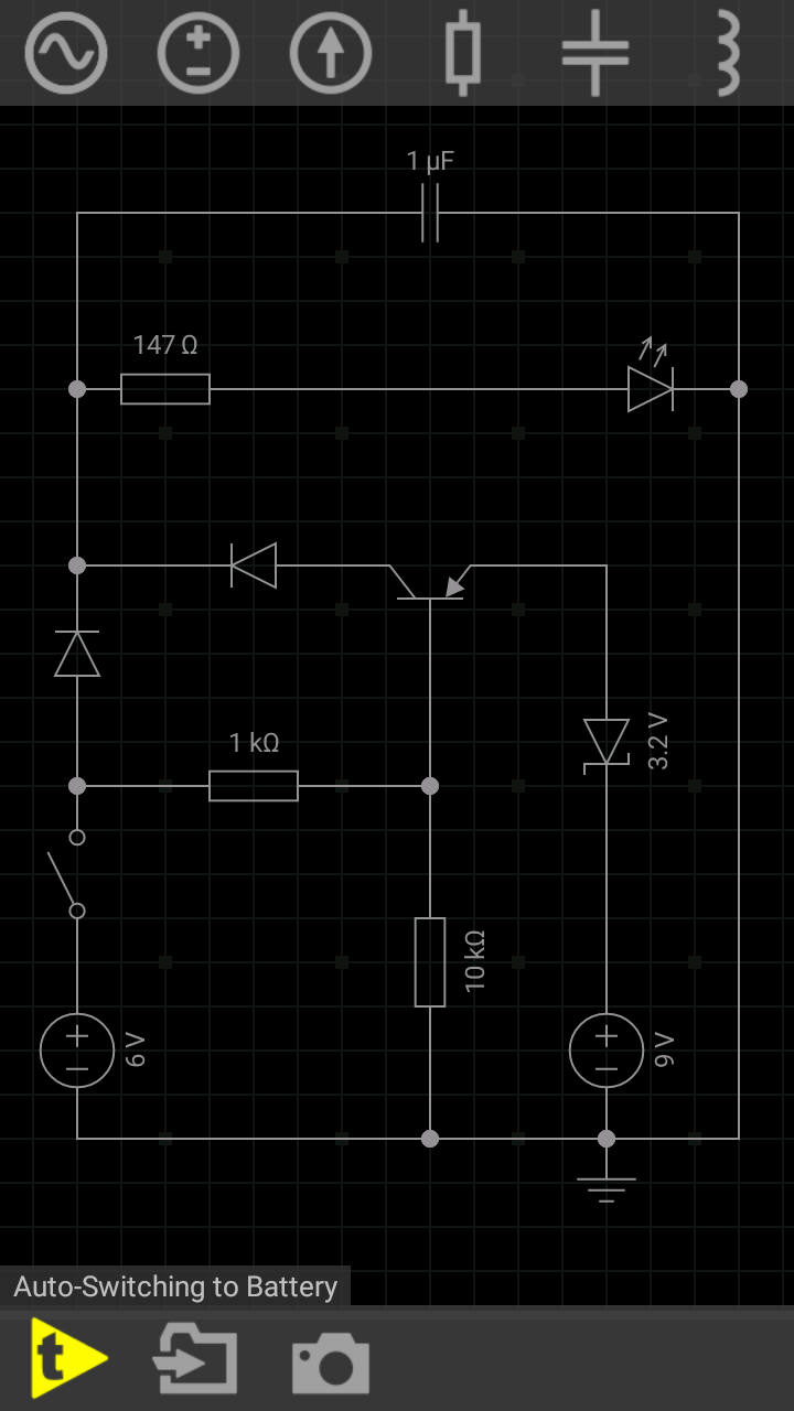
There's a DC 6V adaptor powering load (resistor+LED) when mains AC power is available at home. 1K 10K resistor network biased to PNP transistor holds it in cut-OFF state when line power is available and thus disconnects the battery. But if there's a power cut which is indicated by opening the spst switch placed next to 6V adaptor source, the PNP transistor's base is acted upon by 10K resistor only, pulling base voltage to GND level. Hence PNP switches ON and load is now powered by 9V battery. PN Diodes avoids interference between two sources.

Now you may think "why zener 3.2V is connected to 9V battery?" Ans: During the testing I observed that battery voltage must be less than or equal to that of adaptor's voltage output. So zener simply drops 3.2 volts across it and circuit works fine.

Thus only one source is active at a time. And load is continuously kept powered up even when mains supply cuts OFF unfortunately.

\$\endgroup\$
1
  • \$\begingroup\$ Will this circuit work for alternate voltages, for example 3v for the battery and 5v for the wall adapter? \$\endgroup\$
    – Merlin04
    Commented Dec 31, 2018 at 3:21
0
\$\begingroup\$

I think Carpetpython's circuit is using a center negative DC barrel plug since pin 1 on the jack is the center post.

Invert everything for a center positive DC barrel plug.Flip the diode orientations. With a center positive circuit, the load GND will be slightly above true 0V since there is the diode drop of ~200mV with an average Schottky diode.

\$\endgroup\$
-2
\$\begingroup\$

When the dust settles on this one....the easiest solution is a on/off/on double throw, double pole switch. Namely Battery supply/Off/External power supply.

\$\endgroup\$
2
  • 1
    \$\begingroup\$ But that would necessitate an additional switch of which the consumer/customer needs to be made aware. The suggestions above allow for the continued use of a simple barrel jack with no additional switching. \$\endgroup\$
    – Cloud
    Commented Jan 10, 2017 at 0:33
  • \$\begingroup\$ The switch will probably cost more than a couple of diodes. And if the user forgets to flip the switch, they can run the battery flat, even with the power supply plugged in. \$\endgroup\$
    – Simon B
    Commented Jun 20, 2018 at 22:44

Not the answer you're looking for? Browse other questions tagged or ask your own question.