0
\$\begingroup\$

Recently the idea struck my mind, that I wanted to build a simple but useful emergency light which can run off of any USB port (the specific use case would be to power it from an USB power bank). For that I wanted to design a simple circuit that drives 25 white LEDs (3.2 V, typ.) in parallel.

The question I am facing now is how to achieve a simple design while not using 25 series resistors, as this is just wasteful and not space efficient, for me anyway, I just want to make it more clever somehow.

Is it enough to just step the 5 volts (from the USB) down to 3.2 volts using an off-the-shelf linear regulator like the LM317 and then connect all the LEDs to it in parallel or will the non-ideal characteristics of aforementioned spoil my plan?

I might be overthinking this, which is why I am asking if there might be a better, simpler or more efficient possibility to achieve what I want? :)

\$\endgroup\$
7
  • \$\begingroup\$ The "duplicate" you're referring is only a subset of my question. I am asking a bit further into the topic, I think at least, but there really might not be a better way ... \$\endgroup\$
    – whiterock
    Commented Dec 21, 2015 at 16:38
  • \$\begingroup\$ How exactly is your question different? Simply put, there is no way to connect several diodes in parallel. Period. \$\endgroup\$ Commented Dec 21, 2015 at 16:43
  • \$\begingroup\$ Okay I see, so in simple terms, is it that you are hereby also saying, that there is absolutely no way to power 25 LEDs more efficiently than through resistors? \$\endgroup\$
    – whiterock
    Commented Dec 21, 2015 at 16:45
  • 1
    \$\begingroup\$ Put them in series; use a high-voltage source, e.g. boost converter. Make sure you have enough total power. \$\endgroup\$ Commented Dec 21, 2015 at 16:46
  • \$\begingroup\$ Would that have a higher efficiency? @RespawnedFluff \$\endgroup\$
    – whiterock
    Commented Dec 21, 2015 at 16:47

4 Answers 4

1
\$\begingroup\$

You can use a backlight driver IC which steps the 5V up to 20V+ and power several LED strings (perhaps with I2C brightness control from a micro, such as with the Skyworks AAT1236), however I think your best bet is to simply use series resistors and keep it simple. Especially in keeping with the function of the unit.. parallel strings and resistors are more likely to be functional when you need them. The advantage of the switching regulator would be higher efficiency- with resistors you've got 64% efficiency- a switching regulator might be more like 85%, so the battery might last 1/3 longer.

A linear regulator would simply gather the heat from the resistors into one place, you should use some resistors anyway, and it would degrade the current regulation, so I think you should forget about that. If you were making a toy light in China, putting the LEDs directly in parallel and using the most horrible smallest-chip white LEDs you could find with a single (or a few with a few parallel banks) series resistor(s) might be an option but I would not stoop to suggest it openly.

\$\endgroup\$
3
\$\begingroup\$

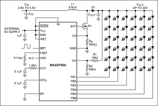
I would never put the LEDs in parallel because there are chips that can do this job properly such as this one from Maxim: -

enter image description here

\$\endgroup\$
1
\$\begingroup\$

1) USB can only supply about 500 mA. You can get a single white LED that is rated for that amount of current.

2) If you put multiple LEDs directly in parallel, small variations in the LEDs themselves will cause them to run different currents in each LED. You basically have to 'ballast' each LED to swamp the differences -- a R does this.

3) A regulator would perform the same function as a resistor in your plan -- both drop the V from 5 to 3.2 V.

4) In an emergency, how is the USB powered ?

\$\endgroup\$
5
  • \$\begingroup\$ The last point is the easiest -- you can assume a laptop or a USB battery bank (phone charging sort). I've got an 18650 version of the latter and if only I could get into it I would add a decent white LED. \$\endgroup\$
    – Chris H
    Commented Dec 21, 2015 at 16:33
  • \$\begingroup\$ 1) I want multiple LEDs though as I on the one hand don't want to deal with the heat such a single LED generates and the other hand I want kind of a panel effect 2) So you're telling me there is no better way? 4) Added it to my original answer => USB power bank \$\endgroup\$
    – whiterock
    Commented Dec 21, 2015 at 16:34
  • \$\begingroup\$ You can use a Fresnel lens if you want to distribute the light from a single led. \$\endgroup\$ Commented Dec 21, 2015 at 16:52
  • \$\begingroup\$ Same heat either way. You consume a current from the 5 V, and while LEDs are efficient, 90 % of the power is still dissipated as heat. Whether you use 1 R, multiple R's, or a linear regulator, it's still the same amount of heat. A DC/DC could help some by eliminating most of the heat in the regulation from 5 V to 3.2 V \$\endgroup\$
    – jp314
    Commented Dec 21, 2015 at 16:56
  • \$\begingroup\$ I ment the heat coming from the LEDs which I can handle easier with a multitude of them as I don't need one big heatsink for one 500 mA LED... \$\endgroup\$
    – whiterock
    Commented Dec 21, 2015 at 17:54
1
\$\begingroup\$

"you are hereby also saying, that there is absolutely no way to power 25 LEDs more efficiently than through resistors" Well, no, not necessarily.

It would be possible to control each LED separately with a switch-mode current regulator. Of course, this means that you would need 25 regulators. While this would be more power-efficient (for some regulators), it would be much more expensive than 25 resistors.

Likewise, it would be possible to make a boost-type current regulator which would provide a much higher voltage to a series string of LEDs.

In any case, I'd recommend a nominal LED current of about 10 mA per LED. LED power dissipation is then $$P = 25\times 10\text{ mA}\times 3.2\text{volts} = 0.8\text{ watts}$$which is well under the nominal 2.5 watts available from a USB port.

And under no circumstances should you even think about connecting 25 LEDs in parallel. LEDs have a negative temperature coefficient for the voltage drop. This means that if you keep all the LEDs at one voltage, whichever one dissipates the most current will get hotter than the others, which will cause it to get hotter, which produces a vicious circle. Since the voltage source must, by definition, be able to provide 25 LEDs worth of current, the most likely result is that the weakest LED will enter thermal runaway and self-destruct, failing open. This will cause the next-weakest to do the same thing, and then the next, etc. This is called "firecracker mode failure", for obvious reasons.

\$\endgroup\$

Not the answer you're looking for? Browse other questions tagged or ask your own question.