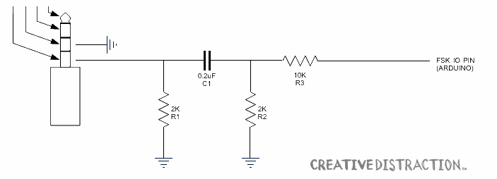
To one way of quickly looking at it,
R3 and R2 form a resistive divider which limits the amplitude of the output to something which will not excessively overdrive the microphone input.
C1 is a DC-blocking or AC-coupling capacitor which passes only change in the signal level, while removing offset in its average, or DC voltage. This is quite normal when moving signals between audio devices or stages.
R1 may exist to help the phone detect that a device is connected. It also functions as something of a frequency dependent voltage divider with C1, ie, a filter.
Overall, the circuit will have additional filter characteristics. You can formally analyze it analytically by writing the capacitor as a frequency dependent impedance and then basically treating it as a network of complex-valued resistors, though the algebra will be a bit expansive. You might consider simulating the behavior in ltspice or various online tools, over a range of audio frequencies. Assume 5v square wave output from the Arduino/MCU.

