2
\$\begingroup\$

I am transmitting RS485 via:

Mono application -> Linux USBTTY device -> RS485 adapter with an added 100R terminator -> ~1m CATV -> SN65176 with an added 100R terminator -> PIC.

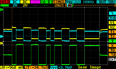
Via debugging I am able to see that transmission from the application to the PIC is successful, and the PIC transmission out of its serial port is also OK. However, when the SN65176 is switched from receive mode to drive mode, the output low level is very noisy (see scope capture):

Scope image of RS482 signals

In this scope capture, channel 1 (blue) is the data (R/D) side of the SN65176, and channel 2 (yellow) is at the RS485 terminal close to the PC.

In this particular case, the first byte was from the PC (00001101) and the second byte was from the PIC. It was supposed to be 00011101 but was received as 00000100.

Here is the relevant Mono/C# port code:

        port = new SerialPort(
            portName: portName,
            baudRate: 115200,
            parity: Parity.None,
            dataBits: 8,
            stopBits: StopBits.One)
        {
            Encoding = ASCIIEncoding.ASCII,
            Handshake = Handshake.RequestToSend,
            DtrEnable = false,
            RtsEnable = false,
            WriteTimeout = 1000 // ms
        };
        port.Open();
// ...
        Port.ReadByte()

The RS232-to-485 adapter is an XS201A. It claims to have fail-safe biasing; however, direct measurement does not support this claim. Perhaps that's because the bias is only enabled when the unit is powered, but I don't consider that particularly fail-safe. It provides no schematic and it's a sealed unit, so it's more difficult to reverse-engineer the thing; however, when driven in the presence of external 100ohm termination on both ends, I see the following voltages:

Va-Vb = 44mV
Va-gnd = 311mV
Vb-gnd = 267mV

The XS201A also claims to use "Automatic Send Data Control", to be port-powered from RTS/DTR/TXD, and to short RTS+CTS and DTR+DSR+CT.

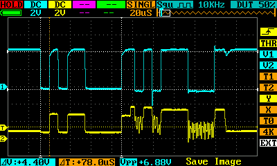
With the SN65176 disconnected, and some slightly different biasing, it seems that the XS201A has an undocumented 4 bits of line drive after which the driver is disabled:

drive timeout

This shows two consecutive 0x33 from the PC. There is one stop and start bit surrounding both bytes, plus the trailing drive timeout.

\$\endgroup\$
15
  • 1
    \$\begingroup\$ It looks to me like contention. Are you sure that the transmitter on the PC side is disabled before the PIC starts transmitting? How is the PC's transmitter-enable signal controlled? Have you looked at both the + and the - sides of the bus and do they both show the problem? \$\endgroup\$
    – Mark
    Commented Jul 12, 2016 at 20:10
  • 1
    \$\begingroup\$ It looks like a baud-rate of around 125k, but I don't see the stop-bit from the PC's transmission. It looks like the PIC is transmitting before the PC is done. It appears from your code that the PC's Transmit-enable is controlled by RTS, but my understanding is that there can be latency before RTS drops, especially through USB. \$\endgroup\$
    – Mark
    Commented Jul 12, 2016 at 20:44
  • 1
    \$\begingroup\$ One thing that might help: I usually put biasing resistors on the bus, so that a tri-stated bus has a voltage about 300 millivolts below center-line (about 2.2v with a 5v bus). That way, it is obvious on a scope when the bus is not driven. It appears that your bus is always driven, which is why I suspect that the two transmitters are overlapped. \$\endgroup\$
    – Mark
    Commented Jul 12, 2016 at 20:47
  • 1
    \$\begingroup\$ @Reinderien - I agree with Mark (+1), from those waveforms your issue is contention. There are various RS-485 adapters which fit the description you wrote, but they don't all operate in the same way e.g. some claim to have "auto-enable" of the RS-485 side. Those require time after they finish transmitting, to stop driving the RS-485 bus. I suggest focussing on just the PC transmitting (tx 1 byte then 5s pause, repeating) and monitor the bus during those pauses. I suspect you will find the RS-485 bus is actively driven for up to an extra character time longer than the transmitted byte itself. \$\endgroup\$
    – SamGibson
    Commented Jul 12, 2016 at 20:52
  • 1
    \$\begingroup\$ Sam makes a good point: some RS-232->RS-485 wait for the transmitter to be idle before disabling the driver. It takes some time to detect idle. What is the RS-485 adapter that you are using? (@SamGibson) \$\endgroup\$
    – Mark
    Commented Jul 12, 2016 at 22:08

1 Answer 1

3
\$\begingroup\$

To summarise the discussion and respond to your test results:

it seems that the XS201A has an undocumented 4 bits of line drive after which the driver is disabled

Agreed, that behaviour fits with what I have seen before on some converters, and thanks for running the test.

It is likely to be a relatively fixed time that the line is actively driven after the transmission by that RS232-RS485 converter, rather than a constant number of bit times irrespective of bit rate. You could change the bit rate significantly and re-test to confirm that the "line driven time after sending" still remains similar to the current ~35 us. You might also find that there is a variation in that "line driven time after sending" depending on the data byte being sent, so I suggest more tests with different bytes to check that.

This was another recent topic here on EE.SE (How is this RS485 Module Working?), where a partial schematic shows the type of circuit which can be used to provide the "automatic" switching between send & receive on RS-485. However those do not switch immediately when a transmission finishes, leading to the sort of behaviour you have observed.

As I see it, some options include:

  • Add delay(s) where needed in your code, to take account of the behaviour of this converter (but you need to test and try to find the maximum "line driven time after sending" first), or ;
  • Use a different RS232-RS485 converter which uses the RTS line to actually switch between Tx and Rx. However you need to check that the RTS signal changes at the correct time and not early (which could truncate the sending). A small "turnaround delay" may still be needed, especially if the distance (i.e. cable capacitance) between devices is large.

You may want to research terms like "RS-485 turnaround delay" or "RS-485 auto-turnaround" for more information and experiences when time-multiplexing multiple transmitters on half-duplex RS-485 buses.

\$\endgroup\$
1
  • 1
    \$\begingroup\$ I'd already started coding the delay before you suggested it, and indeed that has solved the contention that looked like noise. The incoming and outgoing signals now look quite clean... unfortunately, the data coming in are still completely wrong, for some reason. I'll start a new question for that. \$\endgroup\$
    – Reinderien
    Commented Jul 14, 2016 at 21:50

Your Answer

By clicking “Post Your Answer”, you agree to our terms of service and acknowledge you have read our privacy policy.

Not the answer you're looking for? Browse other questions tagged or ask your own question.