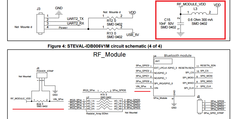
I know the circuit is well tested by STm but, I think, C15 should not be able to provide enough instantaneous power. Does noise suppress by this ferrite bead (cross-over frequency 12MHz) will be same for other circuits if U4 is used?
-
\$\begingroup\$ 600mΩ doesn't sound like very much restriction to me \$\endgroup\$– PlasmaHHCommented Jan 26, 2017 at 11:10
-
\$\begingroup\$ A proper answer requires an exact part listing for the ferrite bead. \$\endgroup\$– Andy akaCommented Jan 26, 2017 at 11:11
-
\$\begingroup\$ For L3 to have any real influence on the powering-up of the module it would need to have a significantly higher inductance value than it has now. I'm thinking like at least a 1000x time higher value. The function of L3 is to stop signals above a couple of MHz to get into VDD, this is for EMI purposes. \$\endgroup\$– BimpelrekkieCommented Jan 26, 2017 at 11:11
-
\$\begingroup\$ "... C15 should not be able to provide enough instantaneous power." - Why not? \$\endgroup\$– marcelmCommented Jan 26, 2017 at 12:20
-
\$\begingroup\$ @Andyaka sorry, I should have mentioned it. L3 Part No. BLM15AG601SN1 \$\endgroup\$– Harsh SinghCommented Jan 26, 2017 at 15:23
3 Answers
They are telling you to put a ferrite bead between the power connection of this module and the power connection to the rest of the board. Perhaps they know the module is susceptible to power supply noise of a certain frequency, but they may also be trying to protect the rest of the circuit from RF being fed back thru the power connection.
In any case, C15 is a decoupling capacitor that they probably tell you to place physically close to the module, right across its power and ground pins. C15 lowers the impedance of the local power net at high frequencies, so a little extra impedance from the power feed doesn't matter. These two impedances are in parallel from the module's point of view. As long as either of them is low, the power into the module will have low impedance and all will be well.
Calculate the impedance of C15 at the RF frequency, and you will see it is substantially lower than that of the ferrite bead. The RF frequency is also high enough that a larger cap would probably have higher impedance at the RF frequency.
There should be no harm in paralleling C15 with a 100 nF cap for better impedance at lower frequencies. However, mount C15 close exactly like they say, then add the 100 nF cap as a extra across C15 without compromising the placement of C15 itself.
-
\$\begingroup\$ I understand that C15 is enough. Is it Okay to use this ferrite bead in my circuit? or should I go through ferrite selection. \$\endgroup\$ Commented Jan 26, 2017 at 15:46
-
\$\begingroup\$ @Harsh: If the datasheet of the module recommends a ferrite bead, then not only is it OK, but you should put one there. \$\endgroup\$ Commented Jan 26, 2017 at 16:00
If you have a concern that the 0.6 Ohm 300 mA ferrite bead will restrict instantaneous current draw requirements of the RF module then the correct thing to look toward is the capacitance value and equivalent series resistance (ESR) of the capacitor C15. This capacitor should be close to the load point (RF module U4) as possible (both the + side and the GND side) and is intended to be the source of the instantaneous current requirements of the module. If the 10nF value of such capacitor is not enough to keep the RF_MODULE_VDD quiet at a nice DC level then the correct approach is to increase its value and/or lower its ESR.
Some designers choose to use multiple capacitors at the C15 location, larger valued ones to provide more high speed current leveling and smaller valued ones to lower the overall parallel equivalent ESR value of the node.
As noted in the comments section of the question, the major purpose of the ferrite bead is to isolate the power source and power distribution network from the high frequency current changes that may exist on the RF_MODULE_VDD node. The power distribution may very well be a longer wiring network and RF existing there is more likely to result in RF emissions problems. With proper design and circuit layout of the RF_MODULE_VDD node the connections will be very short to the C15 capacitor (or its equivalent) and the possibility or RF emissions is greatly reduced.
-
\$\begingroup\$ So C15 will do its job as long as it is placed near RF_MODULE_VDD and this Ferrite bead will not interfere. will it be okay to replace BLM15AG601SN1 by MMZ2012Y601B or should I test and then select ferrite bead. \$\endgroup\$ Commented Jan 26, 2017 at 16:09
you are right, the capacitor should be large enough to sustain current demand. two reasons for that;
- normally there are decoupling capacitors with every component forming a large parallel capacitor network in the entire pcb between the power supply and the components. but when an inductor is introduced it effectively reduces the impact of the rest of decoupling caps and so the capacitance between the ferrite beed and the ic/module needs to be adequate.
- an inductor inherently acts as a resistance to current variations forming a high impedance between supply and the module.
there is this nice article (https://www.murata.com/~/media/webrenewal/support/library/catalog/products/emc/emifil/c39e.ashx )where it mentions in detail about decoupling and filtering.
regarding to your specific problem, the formula for necessary capacitance between FB/inductor and IC is;
C > L/sqr(Z)
where L is the inductance and Z is the powerline impedance needed by the IC. it can be calculated by;
Z = delta V / delta I
delta V is the allowable voltage variations (mostly in 10-100mV) and delta I is the change in current during operation which depends on the IC.

