9
\$\begingroup\$

I have a stepper motor driver breakout board based off the Allegro A4988 chip. I noticed that when the motor is static, it has much better holding torque than when moving. I have a battery operated configuration and a majority of the time the stepper motor is only used to hold a position. The limit setting potentiometer is already on the breakout board so I can't change it with my micro-controller.

Would I able to apply a PWM signal to the enable pin of the motor driver to change the current going into the motor so that I can drive the motor at a higher current level when actively moving and reduce the current for holding position?

I'm mostly interested on the effects a PWM signal will have on the driver circuit's life. Nowhere on the data sheet dose it say you can or can not do something like this.

\$\endgroup\$

4 Answers 4

2
\$\begingroup\$

I'm not sure what you mean by 'the limit setting potentiometer', but (assuming that you mean the current sense resistors \$R_{S1}\$ and \$R_{S2}\$ (which would be an interesting design, those should be matched low-impedance resistors) I read on page 9, in the section Internal PWM Current Control:

The maximum value of current limiting is set by the selection of RSx and the voltage at the VREF pin. The transconductance function is approximated by the maximum value of current limiting, \$I_{TripMAX}\$ (A), which is set by

\$ I_{TripMAX} = V_{REF} / ( 8 R_S) \$

where \$R_S\$ is the resistance of the sense resistor (Ω) and V_{REF} is the input voltage on the REF pin (V).

Do you have access to the REF pin (pin 17)? If so, adjusting this with a DAC will produce the same effect as varying the sense resistors.

If not, the Enable input is probably a better choice than cutting the power or using the sleep or shut-down pins, those would incur a 1 ms delay (per the description on p. 10).

\$\endgroup\$
3
  • 1
    \$\begingroup\$ Sorry, I think the sense resistors are permanently set, the potentiometer is probably adjusting the REF pin (don't know though, don't know enough about electronics). I guess the problem here is that I would end up running two overlapping PWM signals. First, the internal one that uses the sense resistor to control the current, second the one that I'm using to shutdown the FETs. \$\endgroup\$
    – Faken
    Commented Mar 26, 2012 at 2:29
  • \$\begingroup\$ From what I can gather, the chip is using the sense resistor to detect current and adjust it's PWM so that it averages out to whatever current limit I am setting. However, what happens if I suddenly start interrupting that process by toggling the FETs on and off with enable very quickly? It may not affect the full step modes, but what about the micro stepping modes? I know not to use the shutdown or sleep pins, that messes with the logic circuits and may reset my current step position. \$\endgroup\$
    – Faken
    Commented Mar 26, 2012 at 2:32
  • 1
    \$\begingroup\$ You'll need to PWM the enable pin slowly. Take a look at the waveforms on p. 11: You want to be slower than \$V_{STEP}\$'s period but significantly faster than \$t_{off}\$. Interrupting the system during \$t_{fd}\$, while the FET is on, will cause an error in your output voltage. I suggest somewhere between \$10 t_{off}\ < t_{PWM} < 0.1 t_{STEP} \$ as a period for your PWM if that's possible. \$\endgroup\$ Commented Mar 26, 2012 at 14:42
5
+25
\$\begingroup\$

I can see nothing in the datasheet which states that the enable pin cannot be pulsed. It's hard to tell from the internal circuitry if it would cause a problem. The enable pin switches off the external fets, which might mean that the chip is unable to re-circulate current properly, causing voltage spikes. However, I would expect Allegro would have dealt with that situation, since it would happen every time Enable goes high.

If you have a spare driver, then my advice would be to just try it.

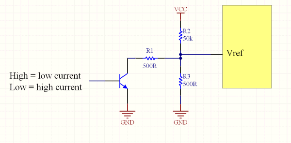
Alternatively, you could reduce the Vref voltage, rather than using PWM. The A4988 will then take care of the current reduction for you nicely. This can be achieved by pulling the Vref pin a little lower with a resistor and either a transistor or a the pin of an MCU which can switch between low and high impedance.

Pulling the Vref pin lower.

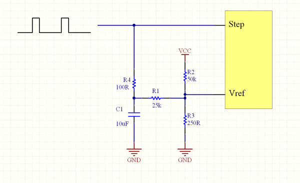
An even better solution might be to make it automatic. Use the step signal to rapidly charge a capacitor which pulls the Vref voltage up. An absence of step signals lets the cap slowly discharge, and with it the Vref voltage and the motor current. The faster the steps, the higher the Vref.

Here's a very rough schematic of how it might work. I just guessed the resistor values, and haven't checked that they would work at all. (Exercise left up to the reader). Very rough schematic

\$\endgroup\$
4
  • \$\begingroup\$ Nice answer, I really like the idea of using the pulse to automatically change the current settings. Unfortunately this is on a breakout board and I don't have access to the Vref pin so I can't do anything with it other than adjusting it with a small plastic screwdriver. \$\endgroup\$
    – Faken
    Commented Mar 28, 2012 at 22:11
  • 1
    \$\begingroup\$ Thanks. It's a shame not to have access to the Vref pin, because it would give you nice smooth current control. Perhaps you could solder a little wire onto the pot? \$\endgroup\$ Commented Mar 28, 2012 at 22:15
  • \$\begingroup\$ I'm torn between which answer to accept. Nether answer actually answers my question. Rocket's answer is very well done and has some really cool concepts but kevin's comments gives me at least some insight as to what to do. \$\endgroup\$
    – Faken
    Commented Apr 3, 2012 at 22:19
  • \$\begingroup\$ Have you tried it yet? I think that's going to be the only way to get a definitive answer. Since there's nothing in the datasheet about it, nobody can really know for sure without trying it. \$\endgroup\$ Commented Apr 3, 2012 at 23:27
1
\$\begingroup\$

No. I mean: you can apply a PWM pulse on the enable pin, but it can interfere with the internal chopping frequency used by the Allegro A4988.

I've tested your idea with different duty-cycles offered by an Arduino (PWM = 490 Hz - IIRC) and it was not working at all: the movement of the stepper was erratic and not regular. Unusable. The only duty-cycle values working were 0% an 100% (i.e. 0 and 255 in the program) .

Seems that modifying the Vref value with some additional circuit is the best approach. But I didn't test it.

\$\endgroup\$
1
  • \$\begingroup\$ Indeed, the only mystery is why so many people jumped on the bandwagon of thinking it was a reasonable idea. Given the chip already has a current control mechanism, it's rather obvious that the correct approach is to work with that mechanism by changing VRef, and not to be slamming the whole thing on and off at a PWM duty cycle. If it's disabled, that should be because it's not needed for a meaningful period of time. \$\endgroup\$ Commented Jan 11, 2021 at 16:00
0
\$\begingroup\$

Sure you can use PWM, but your stepper motor may start to whistle a bit with the PWM frequency. Pick a high frequency that you are unable to hear (>20kHz) or live with the whistle.

\$\endgroup\$
1
  • \$\begingroup\$ The question was about a PWM to the driving electronics, not the motor itself. \$\endgroup\$
    – vsz
    Commented Mar 28, 2012 at 15:20

Your Answer

By clicking “Post Your Answer”, you agree to our terms of service and acknowledge you have read our privacy policy.

Not the answer you're looking for? Browse other questions tagged or ask your own question.