1
\$\begingroup\$

Inspired by Phil's comment on this answer...

Bending the dipole to make it more like a V can also serve to get the impedance to 50 ohms.

Likewise, bending the ground plane leads for a 1/4 wave whip alters the the antenna's impedance.

Backing up a little bit, my understanding of antenna matching is to get the impedance at the feedpoint of the antenna equal to the impedance of the feed line. With Ohm's Law being V=IR, the antenna should be (or can be) designed such that the voltage and current of the standing wave produces the desired impedance.

I have 2 closely related questions:

  • Specifically regarding Phil's comment, why does bending a dipole antenna change its impedance?

  • What's the "mental" model of how an antenna's impedance is determined? I'm trying to get a better intuition of how slightly changing an antenna (like bending the ground plane leads) changes the impedance

\$\endgroup\$
1

2 Answers 2

2
\$\begingroup\$

why does bending a dipole antenna change its impedance?

This is quite a simplistic answer. An antenna has to "interface" with free space.

Free space has an impedance defined by \$\sqrt{\dfrac{\mu_0}{\epsilon_0}}\$.

This turns out to be near-enough 377 ohms when you plug the numbers in.

It's the same as a transmission line - it has \$\sqrt{\dfrac{L}{C}}\$ that defines its high frequency (usually > 1 MHz) impedance.

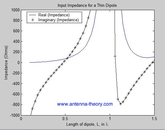
So. if you adjust the dimensions of a piece of coax you get a different value for the characteristic impedance. If you adjust the antenna mechanically you are adjusting it's ability to deliver 377 times more E field to H field. This isn't necessarily a killer because all that your electrical circuit sees, is a radiation resistance that is somewhat lower than (say) 73 ohms for a dipole: -

enter image description here

Notice that 73 ohms is when the diploe is 0.5 wavelengths long and that there is no reactive component. Altering the shape of the dipole inevitably means increasing capacitance and effectively shortening the effective length thus, the impedance can alter quite a bit.

What's the "mental" model of how an antenna's impedance is determined?

It's something I've struggled with for years and in the end I come back to the ratio of E field to H field and how that relates to impedance of free space. If you bend the dipole in on itself (I'm not talking about a folded dipole) then it has more end-to-end capacitance and the E field will reduce. That's how I see it anyway but, for more complex antennas it's a different story.

\$\endgroup\$
0
\$\begingroup\$

To answer your 2 questions at a higher level.

  1. Antennas in general have impedances that are related to their radiation characteristics. That is, some ratio of the radiated electric field to the magnetic field. In turn, the radiation characteristics of the antenna are determined to a very large degree by its size and shape and the existing current distribution. If we begin to distort the shape of an antenna, the input impedance parameters begin to change. In electromagnetics and especially antenna theory, the definition of impedance is not simply R = V/I. The impedances we talk about are usually complex and are heavily dependent on device dimensions and more complicated current distributions. Impedance matching is almost never done as in classic circuits.

  2. A "mental" model would quickly become impractical when trying to visualize the change in impedance for even a simple dipole antenna. The antenna impedance for a dipole requires some calculations that are relatively easy (compared to other radiators) due to the simple symmetric nature of a dipole. The calculations become more complicated and involved if we distort the shape of a dipole and especially so for more complicated antennas.

\$\endgroup\$

Your Answer

By clicking “Post Your Answer”, you agree to our terms of service and acknowledge you have read our privacy policy.

Not the answer you're looking for? Browse other questions tagged or ask your own question.