1
\$\begingroup\$

I need to develop a device that requires 5V power. The device must be powered from 5V (USB) or 12V. I need such a system that will bypass the DC-DC converter when it works from USB and enable the DC-DC converter when it works from 12V.

Will my solution work?

I want to use a voltage comparator with some voltage dividers and voltage reference, so it can short the input and output of a DC-DC converter when the VIN is (let's say) <6V with a P-MOSFET, thus disabling the DC-DC converter and providing the power to the device.

I want to use TPS54331. What will happen if I feed 5V to the DC-DC converter when it configured to output 5V? Will there be a drop? I haven't found this info in the datasheet.

\$\endgroup\$
1

2 Answers 2

4
\$\begingroup\$

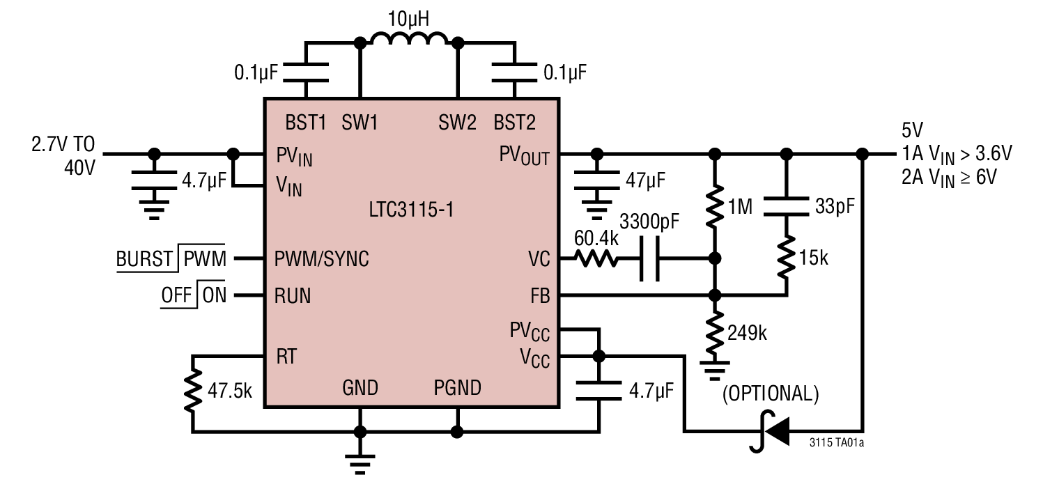
You could save yourself a lot of messing around by using a buck-boost converter like this: -

enter image description here

The USB supply can be fed via a low-volt-drop schottky diode to the input (Vin) and if you have 12 volts also present at the input it will take over and power the converter.

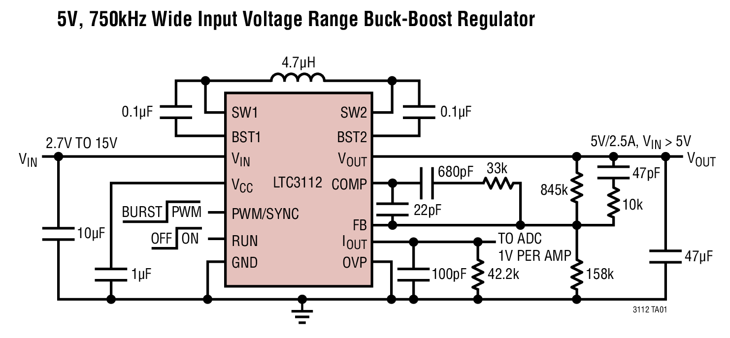
Another option: -

enter image description here

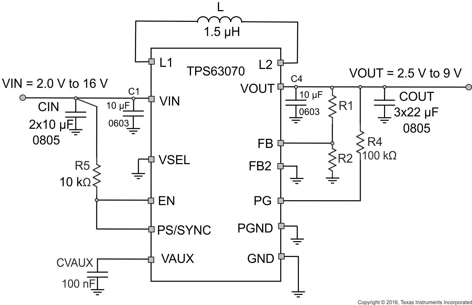
You can get these types of devices from TI too like this: -

enter image description here

\$\endgroup\$
5
  • \$\begingroup\$ Why would I go with buck-boost converter? It is overcomplication. I don't need boost, only buck. Those buck-boost converters are very expensive. TPS54331 is cheap \$\endgroup\$
    – dmitry8080
    Commented Jul 14, 2017 at 11:22
  • \$\begingroup\$ Well I am suggesting a design that works seemlessly and needs no thought or setting up and doesn't require a great analysis to understand that it works. On the cost side you have to weigh up the buck converter cost, the MOSFET cost, the comparator (plus components) cost and the extra PCB space you need. You didn't mention in your question that cost was a vital aim of your design. I am making a suggestion and throwing in options for you to consider. You might also need to consider that applying 12 volts requires automatic disconnection of USB power to prevent back-feed. \$\endgroup\$
    – Andy aka
    Commented Jul 14, 2017 at 11:30
  • \$\begingroup\$ The TPS54331 costs £1.24 in mouser and the TPS63070 costs £2.13. How much is a MOSFET and comparator going to cost plus the various extra resistors/capacitors and possibly a voltage reference for your 6 volt comparison? How much value on peace of mind? \$\endgroup\$
    – Andy aka
    Commented Jul 14, 2017 at 11:36
  • \$\begingroup\$ Andy aka your solution is fine, I like it. It woulf be perfect if I need to make >1000 of my products, but I need only a cople. There is one more thing. Due to magic of chineese economy you can buy not just the TPS63070 chip but whole module with all components for 1.5 US dollar. You cannot do it with this wizzbang buck-boost. \$\endgroup\$
    – dmitry8080
    Commented Jul 14, 2017 at 11:45
  • 3
    \$\begingroup\$ What, you're only making a couple? Then what is the argument about? What has the cost of a few parts got to do with the amount of time you'll spend fixing your design when it doesn't quite do the right thing and dumps 12 volts to the output 5 volt rail and blows something more valuable up? Just how much do you value your time? \$\endgroup\$
    – Andy aka
    Commented Jul 14, 2017 at 12:05
0
\$\begingroup\$

You can do this with a buck converter if you can run a duty cycle of 100% .Common cheap garden variety peak current mode chips do not support D max = 100% .What I did was build one out of discrete components .I used a P channel mosfet switch and a standard shottky freewheel diode .Simple drive kept the parts count down .I only needed 2 amps or so meaning that the P channel switch did not mean a cost penalty .I used this in a product that needed 12 VDC fans to also run on 24 VDC .I did not need to sense impending regulator dropout or have a decision circuit for 12/24 .The system operated seamlessly throughout the desired range of 10 to 32 VDC .When the input volts was less than 12VDC the output just followed the input due to the low RDS on p channel device running at D = 100% .USB currents are not high and V out does not need to be extremely accurate so you should be able to whip something up .The discrete approach that I took was cost effective and useful in other subsequent applications that needed very high input volts .Your input volts are low so you may be able to hang some cheap circuit around your favorite chip so it will support D=100% .

\$\endgroup\$
2
  • \$\begingroup\$ How would you protect the USB power connection from being back-fed by the 12 volts when mistakingly plugged in whilst USB is providing power? \$\endgroup\$
    – Andy aka
    Commented Jul 14, 2017 at 12:25
  • \$\begingroup\$ @ Andy aka .I did not have this on the fan drivers .I suppose you could make some FIODES .There are now chips that do this .They sometimes call these fet assisted diodes . \$\endgroup\$
    – Autistic
    Commented Jul 14, 2017 at 12:40

Your Answer

By clicking “Post Your Answer”, you agree to our terms of service and acknowledge you have read our privacy policy.

Not the answer you're looking for? Browse other questions tagged or ask your own question.