19
\$\begingroup\$

I have a fairly solid background in industrial AC motor control (soft starters, VFDs, etc.) but something that I'm certainly NOT well versed in is brushless DC motors... the type found in every hard drive on the planet.

As far as I can tell, they look identical to your typical star-connected AC induction motor, and the motor controllers look to be very, very similar to the typical three-phase AC controllers I've spent most of my professional life designing.

I can't find much on the real differences between the two, neither from a mechanical construction point of view nor from a control point of view. The closest I seem to find is "they're similar."

Does anyone have any resources or can offer a fairly technical explanation of what the major differences between these types of motors is and their control methods?

\$\endgroup\$
1
  • 1
    \$\begingroup\$ BLDCs are more efficient and less noisy, overall "similar", but not the same. For AC motors, sine reference means sine output (with control circuit), also back EMF is sine, so the motor purs, but efficiency is low. For BLDC, I think the misleading term is DC, they're nothing more than synchronous AC motors with a magnetic twist. Also, the driving is done with Hall transducers (where needed) or by detecting back EMF, so the "philosophy" is different, and the cvasi-sine BLDCs have distorted waveforms, as well, but not quite as the trapezoidal ones. In the end, little differences, but they exist. \$\endgroup\$
    – Vlad
    Commented Oct 9, 2012 at 14:11

4 Answers 4

19
\$\begingroup\$

From All About Circuits:

Brushless DC motors are similar to AC synchronous motors. The major difference is that synchronous motors develop a sinusoidal back EMF, as compared to a rectangular, or trapezoidal, back EMF for brushless DC motors. Both have stator created rotating magnetic fields producing torque in a magnetic rotor.

Construction wise, there is essentially* no difference.
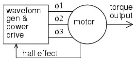
generic motor controller

The motor in the above diagram could be called an "AC Induction Motor" or a "Brushless DC Motor" and it would be the same motor.

The main difference is in the drive. An AC motor is controlled by a drive consisting of a sinusoidal alternating current waveform. It's speed is synchronous with the frequency of that waveform. And since it is driven by a sine wave, it's Back-EMF is a sine wave. A single phase AC Motor could be driven from the wall socket and it would turn at 3000 RPM or 3600 RPM (depending on your country of origin having 50/60Hz mains).

Notice that I said could there. In order to drive a motor from a DC source, a controller, which is essentially just a DC to AC inverter, is required. You are correct in stating that AC motors can also be driven by controllers. For instance a Variable Frequency Drive (VFD) which are, as you said, DC to AC inverters. Although typically they have an AC to DC rectifier front end.

PWM VFD http://www.inverter-china.com/forum/newfile/img/PWM-VFD-Diagram.gif

VFDs use PWM to approximate a sine wave and can come pretty close by varying the pulse widths continuously as seen below:
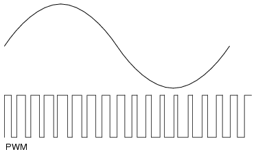
sine versus PWM

While using PWM to approximate a sine wave would produce a nearly sinusoidal Back-EMF wave form ("fuzzy" is the word you used), it's also a bit more complicated to do. A simpler commutation technique is called six-step commutation in which the Back-EMF waveform is more trapezoidal than sinusoidal.

six-step drive

six-step Back-EMF http://www.emeraldinsight.com/content_images/fig/1740300310012.png

And while this "PWM is really poor" as you said, it's also a lot simpler to implement and therefore cheaper.

There are other methods of commutation besides six-step and sinusoidal. The only other one that is really popular (in my opinion) is space vector drive. This has about the same complexity as sinusoidal drive but make better use of the available DC bus voltage. I'm not going to go into detail on space vector as I think it will only muddy the waters of this discussion.

So those are the differences in the drive techniques. The waveform used to drive AC motors is typically sinusoidal and could come directly from an AC source or could be approximated using PWM. The waveform used to drive DC motors is typically trapezoidal and comes from a DC source. There is no reason why the drives couldn't be swapped though there would be a minor hit to efficiency.

*esssentially

Above I said that the construction of the two types of motors is essentially the same. In both cases, AC Induction motor and Brushless DC motor, we are talking about motors that have wound stators instead of permanent magnets. That makes them "Universal motors":

One advantage of having wound stators in a motor is that one can make a motor that runs on AC or DC, a so called universal motor.

However, there is a slight difference in the winding. Motors designed for use with AC are sinusoidally wound while motors destined to be used with DC are trapazoidally wound. Something that has bugged me for years is that I cannot find a simplified diagram that shows the difference. If I was given the stator of a motor, I would have no idea wether it was wound sinusoidally or trapazoidally. The only way I know of to tell the difference is to back drive the motor by connecting a drill to the shaft and looking at the Back-EMF. You will either see a nice sine wave or more of a trapezoid as shown in the image above. As I said above, using the incorrect type of drive would result in a slight performance hit but it would other wise work.

More often than not, Brushless DC motors are built with permanent magnets on the rotor. While that would be a difference from a squirrel-cage motor, as long as the stator is a wound stator and not a permanent magnet stator (as seen in brushed DC motors), both designs are essentially "universal motors":
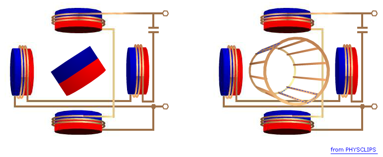
PM versus squirrel-cage

The permanent magnet side of the above diagram shows a two pole motor. The number of poles controls the torque ripple. The more poles the smoother the torque curve. But the number of poles makes no difference from an AC versus DC perspective.

The connection of the stator windings, delta versus star, also does not affect the drive method. And in fact, you can switch between the two while it's running:
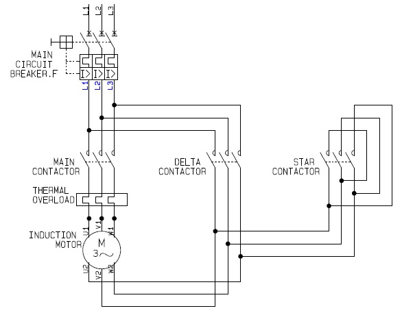
delta star switch-over

The difference there is that delta will draw more current and therefore produce more torque. For more information on the relationship or current to torque or voltage to speed, see my answer to this EE.SE question.

\$\endgroup\$
9
  • \$\begingroup\$ Thank you for the detailed answer but your control method matches exactly what an AC inverter does (chopped DC using IGBTs or FETs to simulate a sinusoidal current waveform). You showed a delta-connected motor which is also common, but doesn't answer what is different between a BLDC and standard squirrel-cage AC induction motor. The back-emf should be pretty close to a sinusoid unless your PWM is really poor; the current waveform of a VFD is a "fuzzy" sine wave in most cases... is the PWM used for BLDCs not the same? \$\endgroup\$
    – akohlsmith
    Commented Oct 8, 2012 at 23:33
  • \$\begingroup\$ @AndrewKohlsmith Honestly I wasn't happy with my answer either but I got interrupted in the middle and had to run. I've expanded my answer quite a bit and hopefully made it a bit clearer. I've also included answers to some of your additional questions in your comment. Let me know if the difference is still not clear. \$\endgroup\$ Commented Oct 9, 2012 at 15:52
  • 1
    \$\begingroup\$ That is a fantastic answer. I had not known about trapezoidally wound coils before; I will ask one of my motor shop buddies about it. The star-delta starters are something I've been exposed to in my distant past, along with autotransformer starters. The six-pulse (and more common for EMI/RFI/harmonic 18-pulse) designs are what I've commonly seen on the rectifier front-ends, not so much on the motor side, since PWM control gets you pretty close to a nice clean sinusoidial current waveform. All said, excellent answer! \$\endgroup\$
    – akohlsmith
    Commented Oct 9, 2012 at 17:47
  • \$\begingroup\$ space-vector (and flux-vector) designs have a motor model in software and use a pair of functions (Clark and Park) to convert the current waveforms to magnetizing and torque-producing vectors which are then rotated and converted back to current vectors. These new current vectors are then used as setpoints to alter the PWM to try to achieve the calculated currents. The idea is to more accurately control the motor than by a straight V-Hz scaling. \$\endgroup\$
    – akohlsmith
    Commented Oct 9, 2012 at 17:54
  • \$\begingroup\$ It seems that both BLDC and squirrel-cage induction motors could have the same control algorithm, as long as the motor model could either detect or select the type of motor winding. Permanent magnet (synchronous) motors would have a different control mechanism as the motor slip would be significantly lower. \$\endgroup\$
    – akohlsmith
    Commented Oct 9, 2012 at 17:55
15
\$\begingroup\$

I'm a little late in answering this question and I can't yet reply directly to embedded.kyle above, but I wanted to correct a little misinformation given above. My expertise is motors, not controls, BTW.

1) "Universal motors" are entirely different than BLDC or induction motors. Universal motors have wound stators and armatures and have brushes. Just because the stator is wound doesn't make it a universal motor ... the link embedded.kyle linked about universal motors is just comparing them to PMDC brushed-type motors.

2) BLDC motors always have magnets on the rotor. As I said above, they are never referred to as universal motors. Universal motors are entirely different beasts.

3) Regarding trapezoidal verses sinusoidal, there is no standard way to wind induction motors and brushless motors (I dislike the terms "sinusoidally wound" and "trapezoidally wound" for reasons I'll explain below). In general, induction motor designers try to produce an air gap MMF and flux that is sinusoidal. This is generally done with what is called a "distributed" winding. All this means is that instead of a coil with T number of turns, you have multiple coils with varying number of turns to approximate a sinusoid.

Brushless motors can have a have back-emf's that look more sinusoidal or look more trapezoidal, as embedded.kyle mentioned. However, you'll never get a purely sinusoidal or trapezoidal back-emf ... how motors are designed and made prevent that from ever happening. It's always somewhere in between. The shape of the back-emf is determined by many things - how it is wound, the ratio of stator teeth to rotor magnets, the shape of the lamination teeth, the shape of the rotor magnets, etc. This is why I dislike the terms "sinusoidally wound" and "trapezoidally wound" - the back-emf depends on other things than how it is wound. You can drive any brushless motor with either a "trapezoidal" drive or a "sinusoidal" drive. Generally (but this isn't universal), if you have a motor with a more or less trap back-emf that is meant to be paired with a trap drive, motor manufacturers will refer to this as a BLDC motor. Likewise, if you have a motor with a more or less sinusoidal back-emf that is meant to be paired with a sine drive, motor manufacturers will refer to this as a BLAC motor. But either of these types of motors can be run with either type of drive.

4) The link embedded.kyle pointed to on Oct 23 at 19:06 doesn't show the difference between sine and trap windings. I'll probably leave a comment there, too, but the difference between those two is that one is a lap winding and one is a concentric winding.

\$\endgroup\$
2
  • \$\begingroup\$ If I could rate you more than +1, I would do it. And if I could distribute an accepted answer between two answers I would certainly do it. Thank you very much. I did not realize that ALL BLDCs had permanent magnet rotors. This would affect the control algorithm in subtle ways, which is one of the other things I was trying to determine. Thank you! \$\endgroup\$
    – akohlsmith
    Commented Oct 30, 2012 at 23:57
  • 1
    \$\begingroup\$ @Brad - This is nit picking, however, it would have helped me if the answer used the word "trapezoidal" instead of "trap", or established "trap" is a synonym for "trapezoidal", and the same with "sinusoidal" and "sine". I have an impairment which has as similar effect to dyslexia, so I read and reread some sentences imagining that I had 'gone a bit wonky', when it was just the terminology had changed. Otherwise, I found your answer very helpful, adding a lot for me beyond the first answer, and so I +1 it. \$\endgroup\$
    – gbulmer
    Commented Aug 6, 2014 at 16:59
1
\$\begingroup\$

According to Wikipedia, brushless DC motors are permanent magnet synchronous AC motors with integrated inverter and rectifier, sensor, and inverter control electronics. I'm not too familiar with AC motors, but I think brushless DC motors would be best classified as a sub-set of AC motors from a functional point of view.

There might be some other differences pertaining to application, too. For example the difference between stepper motors and brushless DC motors is usually the intended application and servo motors refers to a motor (usually but not always a brushed DC motor) with integrated rotational position sensors.

\$\endgroup\$
1
  • \$\begingroup\$ Right; the question is specifically about the "raw" motor differences and the control strategy differences. As far as I'm able to determine you would drive a brushless DC motor the exact same way you'd drive an AC induction motor, which is typically with a three-phase PWM waveform approximating a three-phase sine wave with the correct amplitude and frequency (V-Hz ratio) to achieve maximum torque for a given rotational speed. \$\endgroup\$
    – akohlsmith
    Commented Oct 9, 2012 at 13:40
1
\$\begingroup\$

I was a little bit confused by some of the answers above, as some were right and wrong at the same time. I HAVE NO EXPERTISE! . That said: Rotary electric Motors may

  1. Have inner or outer stator thus outer or inner rotor
  2. Have permanent magnets on either stator or rotor , or have coils on both
  3. Use a roto mechanical way of switching on and off coils or use a roto electronic way and being synchronous OR use induction AC and slip and being asyncronous Examples: a) permanent magnet on outside stator and brushed coils on the rotor and DC feeding synchronous (typical dc small toys motors) b) permanent magnet on inside rotor and coils on outside switcing roto electronically dc fed synchronous commutation ( typical brushless dc) c) Coils on both rotor and stator, roto mechanical commutation, Dc or Ac fed synchronous ( typical drill motors ) d) Coils on the external stator, squirell cage coils on the rotor, induction slip coupling Ac fed asynchronous ( typical induction motor to be found on fans ) To be noted: when commutation is roto mechanical it is synchronous because commutation is in phase with the rotation by construction. Roto electronic commutation uses sensor to commute in phase with rotation. Cases a) and b) are very similar the difference being in the commutation. Starting from a) inverting stator and rotor thus inner coiled stator and outer magnetic rotor and changing mechanical commutation to roto electronic we arrive to another version of brushless motor used e.g. in floppy drives. I didn't examined reluctance motors.
\$\endgroup\$

Your Answer

By clicking “Post Your Answer”, you agree to our terms of service and acknowledge you have read our privacy policy.

Not the answer you're looking for? Browse other questions tagged or ask your own question.