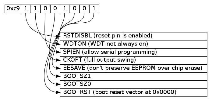
You can play with something with graphviz and dot. Those are the tools doxygen uses to create the diagrams. It is not exactly what you are searching for, but it is fast and easy to script and the output is kind of nice looking (even thou it is a little hard to follow some lines...)
This example will generate something like this

To do this you first create a file called byte.dot
digraph structs {
node [shape=plaintext]

struct1 [label=<
<TABLE BORDER="0" CELLBORDER="1" CELLSPACING="0" ALIGN="left">
    <TR>
        <TD>0xc9</TD>
        <TD PORT="f0"> 1 </TD>
        <TD PORT="f1"> 1 </TD>
        <TD PORT="f2"> 0 </TD>
        <TD PORT="f3"> 0 </TD>

        <TD PORT="f4"> 1 </TD>
        <TD PORT="f5"> 0 </TD>
        <TD PORT="f6"> 0 </TD>
        <TD PORT="f7"> 1 </TD>
    </TR>
</TABLE>>];

struct2 [label=<
<TABLE BORDER="0" CELLBORDER="1" CELLSPACING="0" >
    <TR> <TD ALIGN="left" PORT="f0"> RSTDISBL (reset pin is enabled) </TD> </TR>
    <TR> <TD ALIGN="left" PORT="f1"> WDTON (WDT not always on) </TD> </TR>
    <TR> <TD ALIGN="left" PORT="f2"> SPIEN (allow serial programming)  </TD> </TR>
    <TR> <TD ALIGN="left" PORT="f3"> CKOPT (full output swing) </TD> </TR>

    <TR> <TD ALIGN="left" PORT="f4"> EESAVE (don't preserve EEPROM over chip erase)  </TD> </TR>
    <TR> <TD ALIGN="left" PORT="f5"> BOOTSZ1 </TD> </TR>
    <TR> <TD ALIGN="left" PORT="f6"> BOOTSZ0 </TD> </TR>
    <TR> <TD ALIGN="left" PORT="f7"> BOOTRST (boot reset vector at 0x0000) </TD> </TR>
</TABLE>>];

struct1:f0:s -> struct2:f0:w;
struct1:f1:s -> struct2:f1:w;
struct1:f2:s -> struct2:f2:w;
struct1:f3:s -> struct2:f3:w;

struct1:f4:s -> struct2:f4:w;
struct1:f5:s -> struct2:f5:w;
struct1:f6:s -> struct2:f6:w;
struct1:f7:s -> struct2:f7:w;
}
Then run one of those commands.
dot -Tpng byte.dot -o byte.png
dot -Tps  byte.dot -o byte.ps
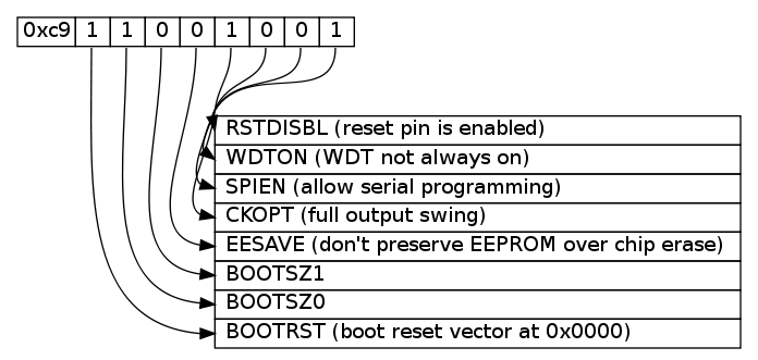
Maybe it will be nicer if we do not cross all the lines in the middle?

I just switched the named in the second table from f0..f7 into f7..f0.
<TABLE BORDER="0" CELLBORDER="1" CELLSPACING="0" >
    <TR> <TD ALIGN="left" PORT="f7"> RSTDISBL (reset pin is enabled) </TD> </TR>
    <TR> <TD ALIGN="left" PORT="f6"> WDTON (WDT not always on) </TD> </TR>
    <TR> <TD ALIGN="left" PORT="f5"> SPIEN (allow serial programming)  </TD> </TR>
    <TR> <TD ALIGN="left" PORT="f4"> CKOPT (full output swing) </TD> </TR>

    <TR> <TD ALIGN="left" PORT="f3"> EESAVE (don't preserve EEPROM over chip erase)  </TD> </TR>
    <TR> <TD ALIGN="left" PORT="f2"> BOOTSZ1 </TD> </TR>
    <TR> <TD ALIGN="left" PORT="f1"> BOOTSZ0 </TD> </TR>
    <TR> <TD ALIGN="left" PORT="f0"> BOOTRST (boot reset vector at 0x0000) </TD> </TR>
</TABLE>>];


