A BLDC machine is part of the PMSM family. From a machine perspective a BLDC machine will produce higher torque and also higher efficiencies at the expense of higher torque ripple (the commutation dips are large!).
*NOTE: IPM and PMSRM push the efficiency and performance higher for PMSM topologies. These are excited with sinusoidal waveforms
Since BLAC and BLDC machines are PMSM you can excite either with either methods (BLAC with quazi-squarewave and BLDC with sinusoidal). You will gain some of the benefits with crossing their drive topology but not equally when compared to a machine (for the same framesize) optimised for the specific backEMF profile
How is SVM different from sinusoidal PWM. I thought SVM is just
sinusoidal PWM on all 3 phases.
What is the difference between SVM and sinusoidal PWM when used with
BLDC motors , and how does SVM utilise the DCLink voltage better?
I am highlighting that one part specifically because of the opening paragraphs. How you generate the PWM is agnostic to the type of motor being used. "when used with BLDC motors" is a red herring.
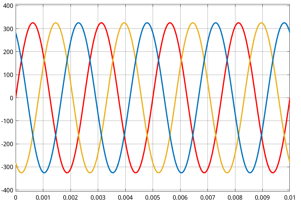
Sinusoidal PWM and SVPWM both produce sinusoidal currents,both compare a reference voltage signal to a triangular carrier (for PWM generation). The difference is in how they produce this. The key difference is: SPWM operates on a per-phase basis independently while SVPWM works on all three at once.
Both start off with a sinusoidal phase demand reference (either due to the output of an inverse Clarke-Park transform or via some other source)

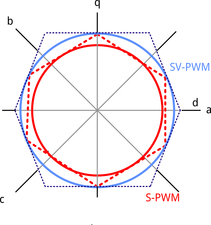
This is where there is a divergence in methods. For S-PWM, these references are directly compared to the triangular carrier. As a result it can only ever produce an output phase voltage that of 0.5Vdc (when compared to the neutral of the motor) because the inverter will switch about a virtual midpoint.

Even if you were to include a single DCLink capacitor, the "virtual midpoint" would be that of the neutral and equally the star of the motor is a "virtual midpoint". SPWM can therefore only produce +0.5Vdc and -0.5Vdc. At some point you will run out of voltage, voltage needed to push current into the machine.
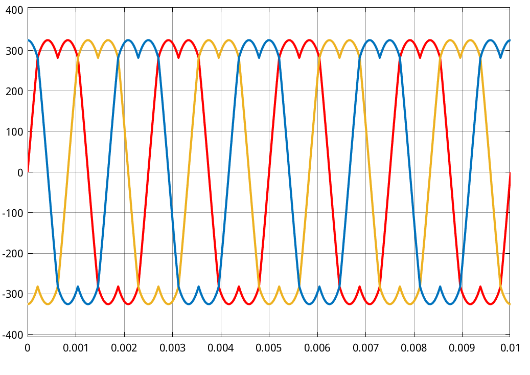
So how is SVPWM different? Well because it works on the 3-phase vectors as a whole and tries to synthesis all at once (rather than independently), the resultant voltage waveforms are different. How these are generated (the exact timing, the resultant line-line, the mathematical equations) are an implementation specific point but the result are voltage demands seen below. These are directly compared with the triangle wave carrier to create the needed PWM

So what is so special about these voltage waveforms? Their shape presents a root-locus which utilises more of the available DC-link. but how? The common mode voltage swing

As mentioned previously, S-PWM is centred around the midpoint of the DClink, with SVPWM, this midpoint moves (due to the dips, the same dips if 3rd harmonic injection was used). Because there is a resultant shift in the CM-voltage, a higher potential difference can be used on a cycle-by-cycle basis, thus extending the potential voltage available to generate line-line voltages.


The downside is the starpoint of your motor now has a common-mode component, which causes some serious considerations when you are dealing with EMI.
Finally the reason I stated Likewise if you have gone to the effort to implement a FOC you might as well implement a SVM block to maximise the utilisation of your DClink voltage was the beauty of quazi-squarewave control is it is simple. If you are wanting to go the route of FOC, this will produce sinus outputs with a fair amount of computational overhead. A systematic decision must have been made to utilise FOC (performance possibly) and thus to utilise SVPWM is a tiny additional computational overhead ontop of FOC
--edit--
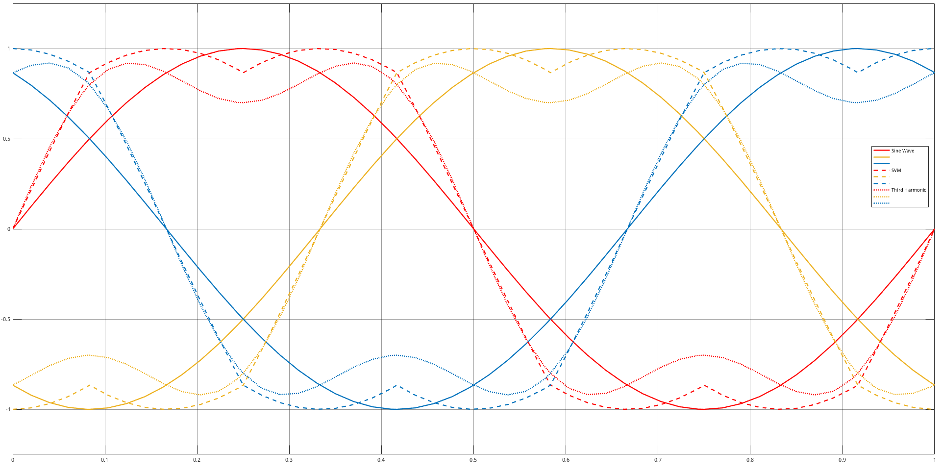
Adding visual overlay of the reference voltage waveforms for
- Sinusoidal
- SV-PWM
- 3rd harmonic injection


