0
\$\begingroup\$

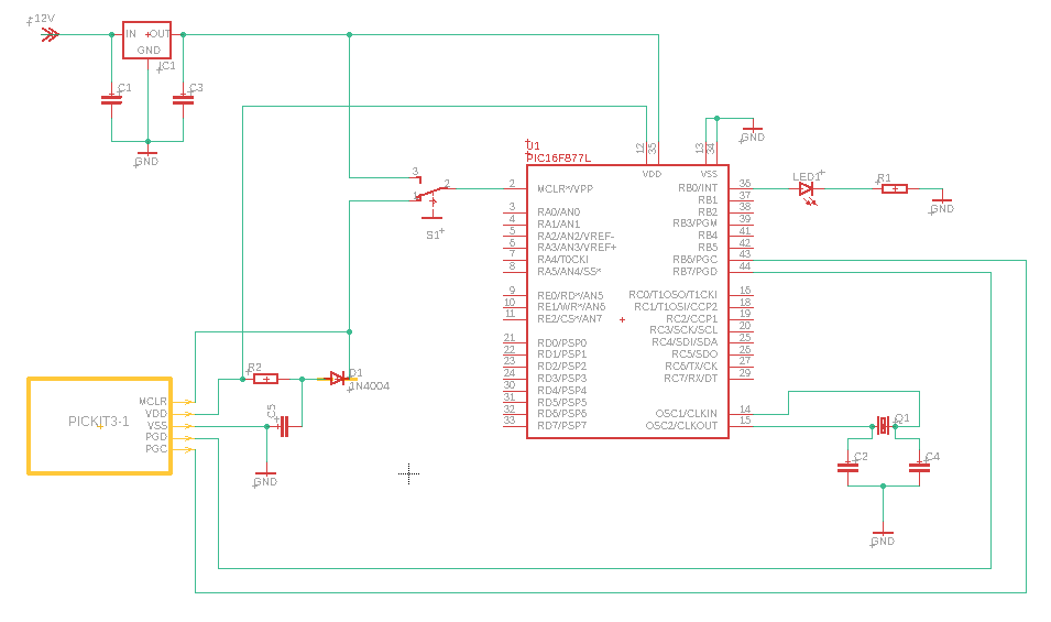
After a lot of trials & errors I was able to come up with a circuit to blink an LED using a PIC16F877A microcontroller.

enter image description here

Components I use are,

  • PIC16F877A
  • LM7805
  • 20MHz Crystal Oscillator
  • IN4007 Diode
  • 300R Resistor
  • 10k Resistor
  • 22 Ceramic Capacitor
  • 104 Ceramic Capacitor
  • 224 Ceramic Capacitor

My question is, whether this circuit is good enough for learning purposes, or does it has any serious issues with it. These are my concerns,

  1. While programming, S1 switch is put to position 1. After programming, it is put to position 3. Is it the wrong approach? I actually change the position of the jumper wire (No sliding switch).
  2. Also, after programming, I have to remove all the PICkit3 connections otherwise the LM7805 becomes hot.
  3. Further, when I run after programming & removing the PICkit wires, I get a slight shock when touching the metal silver head of LM7805.
\$\endgroup\$
5
  • 1
    \$\begingroup\$ You can power chip ONLY from your power ic, you don't have to power it from PICkit even when programming; Just remove pickit's Vdd connection completely. But Grounds MUST be connected. PICkit 4 quick start guide recommend 50k resistor between MCU's Vdd and Vpp. When you switch to position 3, you connect Vdd and Vpp without resistor. Try adding it first and not connecting Vdd and Vpp directly. \$\endgroup\$
    – Ilya
    Commented Jun 8, 2020 at 9:32
  • \$\begingroup\$ @Ilya Thanks but, I get the following error during programming process, after I remove PICkit's VDD connection to pin12 on the diagram. Failed to program device Target Vdd not detected. Please ensure the target device is connected. \$\endgroup\$
    – RukshanJS
    Commented Jun 8, 2020 at 10:09
  • \$\begingroup\$ you MUST connect grounds of: Power IC, MCU and PICKit with each other (even if PICKit Vdd supply pin is disconnected). What what I see in the comments here, that could be the issue. \$\endgroup\$
    – Ilya
    Commented Jun 8, 2020 at 10:16
  • \$\begingroup\$ @Ilya sorry to bother you, but I have connected those to a command GND. But I wonder to where shall I connect MCLR of PICkit? Connecting to MCLR of MCU does not work. I am learning this stuff :-) \$\endgroup\$
    – RukshanJS
    Commented Jun 8, 2020 at 10:19
  • 1
    \$\begingroup\$ Have a look at this little document: ww1.microchip.com/downloads/en/devicedoc/50002721a.pdf there is a guide on page 2. It's for PICkit 4, but the idea is exactly the same. As well as your MCU. See what connects to what. If you're completely inexperienced, I would suggest building a few circuits with arduino first to feel how stuff works without diving into horrible things like setting configuration bits and other scary stuff \$\endgroup\$
    – Ilya
    Commented Jun 8, 2020 at 10:41

2 Answers 2

1
\$\begingroup\$

Leave VDD unconnected from the programming header and connect the microcontroller VDD pins to your power supply. You are now shorting the power supplied from pickit and your own circuit. When the programmer is not present you are no supplying to the other VDD pin.

You get "shocked" because the power supply you are using probably doesn't have grounding connection and is leaking half of the mains voltage through bypass caps to the output (common mode in +12 V and 0 V pins).

\$\endgroup\$
3
  • \$\begingroup\$ @stackerRook Power supply grounding is an EXTREMELY good idea - the voltage that you feel can destroy electronic devices. Your psu has "Y capacitors" as noise filters and without a 3 wire mains lead with ground this couples Vmains/2 to the floating ground - typically via 0.01 or 0.001 uF caps. \$\endgroup\$
    – Russell McMahon
    Commented Jun 8, 2020 at 10:38
  • \$\begingroup\$ I find it very odd that although contradicting Ralph's & Ilya's answers, when I connect the VDD of PICkit to a VDD of MCU, everything works fine, except for the little shock. I think you are right but I don't know what is going on. I'll post an updated circuit diagram. \$\endgroup\$
    – RukshanJS
    Commented Jun 8, 2020 at 10:48
  • \$\begingroup\$ Many incorrect circuits seem to function well for a while. If in doubt, refer to manufacturer datasheets, application notes. Evaluation board schematics are often helpful too. The little shock or vibrating sensation will remain unless you change the power supply to a better isolated or well grounded one. \$\endgroup\$
    – Ralph
    Commented Jun 8, 2020 at 11:14
0
\$\begingroup\$

I got it working the way I want by adjusting the circuit as below. Thank you very much to all of you who helped.enter image description here

Instead of connecting to a wall adapter to get 12V, I just used a 9V battery. Now I got no considerable shock, and also everything works fine.

Hopefully, this circuit doesn't violate any norms or standards. Comments are more than welcome.

\$\endgroup\$
2
  • 1
    \$\begingroup\$ Good that you're making progress. @Ilya suggested R2 value 50k - seems reasonable. Connecting PICkit3 VDD pin to 7805 OUT is not a good idea. Use one OR the other. Be aware that some PICkit3 units have problems generating VDD from some USB sources. Frustrating - have seen this myself but cannot suggest a sure-fire workaround. \$\endgroup\$
    – glen_geek
    Commented Jun 8, 2020 at 13:30
  • \$\begingroup\$ This was a project that I was working on. I've created a whole blog post about how I did it. If anyone interested, check it out here at my website, rukbook.com/simple-led-blinking-with-pic16f877a. Thanks for the awesome help! I'm more than happy for any feedback. \$\endgroup\$
    – RukshanJS
    Commented Jun 8, 2020 at 18:34

Your Answer

By clicking “Post Your Answer”, you agree to our terms of service and acknowledge you have read our privacy policy.

Not the answer you're looking for? Browse other questions tagged or ask your own question.