0
\$\begingroup\$

How can one control on/off and direction for a single phase reversing AC motor using relays? I have wired an AC motor correctly with 5 wires: green (ground), red (live), black (neutral), blue (coil 1), and yellow (coil 2).

If AC current is passed between [red+blue] and [black+yellow] it spins clockwise.

If AC current is passed between [red+yellow] and [black+blue] it spins counterclockwise.

I understand that speed cannot be controlled with relays and do not need that. For a DC motor, I can use two relays and diodes to achieve this functionality as outlined by this question How to use a flyback diode on a +/-12V motor

If it helps, this is the motor I am using https://www.baldor.com/catalog/L3503#tab=%22drawings%22, but I think the suggestion should be generalizable (please explain if I am wrong and the suggestion is motor specific).

\$\endgroup\$
4
  • \$\begingroup\$ A selling page for the motor (especially if shamazon, peebay or bang bad or malibaba/express) is insufficient information. The motor should have some form of data sheet that explains how it is wired up. \$\endgroup\$
    – Andy aka
    Commented Jan 6, 2021 at 14:21
  • \$\begingroup\$ I do not think the 'solution' is motor specific, but I have updated the question accordingly. Nice puns btw haha. \$\endgroup\$
    – grahmW
    Commented Jan 6, 2021 at 15:19
  • \$\begingroup\$ Do you want to connect for 115V or 230V? Does the motor have connection posts 1 thru 6 as shown on the label? \$\endgroup\$
    – user80875
    Commented Jan 6, 2021 at 15:47
  • \$\begingroup\$ I have it correctly wired for 115V; I am able to spin the motor in the desired direction by manually switching the lines indicated in the drawing (red and black). \$\endgroup\$
    – grahmW
    Commented Jan 6, 2021 at 15:50

3 Answers 3

0
\$\begingroup\$

I am not entirely sure I parsed your question correctly, but...

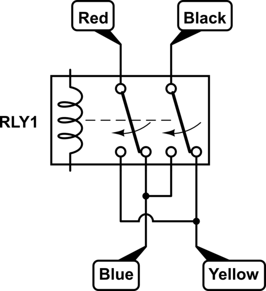
The circuit below uses a DPDT (double pole, double throw) relay.

If the coil in the circuit is un-energized, the red wire will be connected to blue, and the black to the yellow.

If the coild is energized, the red will be connected to yellow, and the black to the blue.

Note that if one of your relay contacts becomes "sticky", you may create a short when the relay coil changes state, so it is best to fuse both the red and black wires, or the blue and yellow wires.

schematic

simulate this circuit – Schematic created using CircuitLab

\$\endgroup\$
0
\$\begingroup\$

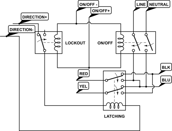
Here is one approach. The direction relay is shown as a latching relay which is locked out when power is applied because the motor direction should not be changed when the motor is under power or immediately after a loss of power. You may also want to add some type of guard against powering down, changing direction, and powering back up while the motor is still coasting, especially if you are driving a large inertial load.

schematic

simulate this circuit – Schematic created using CircuitLab

\$\endgroup\$
0
\$\begingroup\$

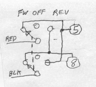
You can use a double-pole, double-throw, center-off switch as shown below. You should keep the switch in the OFF position until the motor coasts to a stop. The motor is not likely to do well if switched while running. It will not reverse at all if switched while running if you don't wait in the off position for the centrifugal switch to open.

You can use a SPDT relay as shown in another answer if you switch the relay only when the motor is stopped.

enter image description here

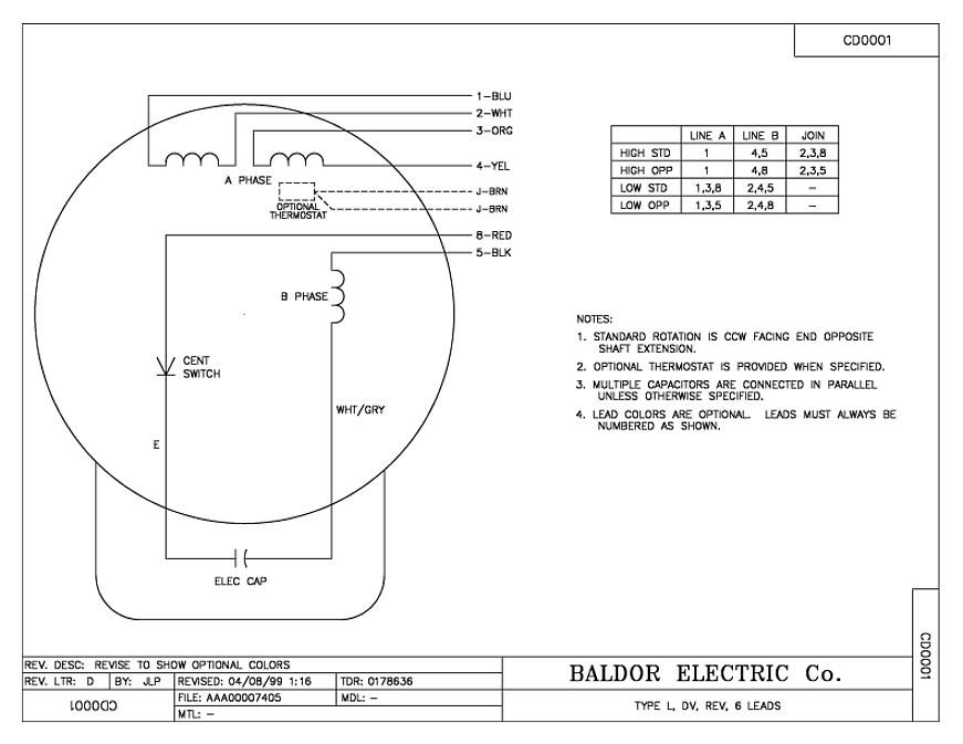
Here is the motor diagram:

enter image description here

\$\endgroup\$

Your Answer

By clicking “Post Your Answer”, you agree to our terms of service and acknowledge you have read our privacy policy.

Not the answer you're looking for? Browse other questions tagged or ask your own question.