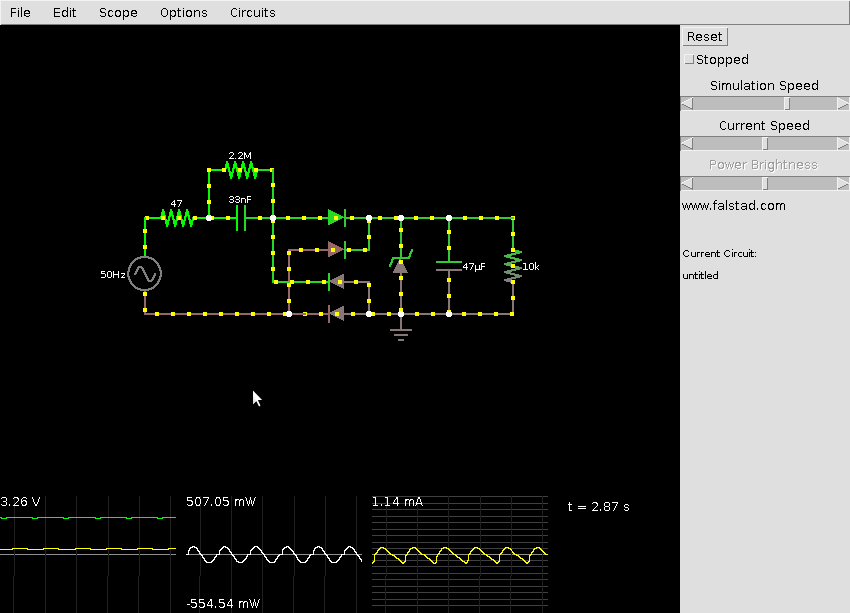
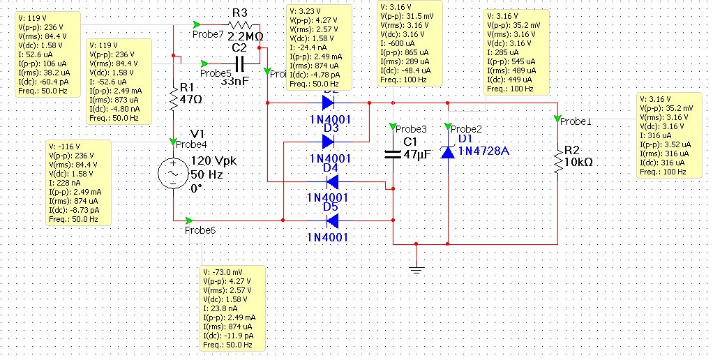
This power supply only works as designed (provides an arguably constant voltage) by consuming a constant power from AC mains. It is an AC current source, as opposed to a voltage source.
Therefore you need a diode bridge, an energy accumulator (capacitor) and a voltage regulator to transform it into DC.
However, since a constant energy is drawn from AC mains, any energy not consumed by the load has to be dissipated. That is why a Zener diode is used; any excess energy is dissipated in the form of heat in the Zener diode. If it were a linear regulator, input voltage would climb above its maximum Vin to the point where it burns up. And because the amount of power drawn from AC mains depends on AC voltage and frequency (because of the reactance), the Zener diode also helps maintain a constant voltage in the variance of AC mains voltage and/or frequency.
Efficiency:
The power factor is not the efficiency of the power supply and neither is it Vout/Vin. Efficiency is Pout/Pin = (Vout*Iout)(Vin*Iin). In a linear power supply, Iout could be considered to be the same as Iin (if you discard Iq) and therefore efficiency can be simplified as Vout/Vin. In a capacitive power supply however, Pin is constant, so its efficiency will totally depend on how much of the available power the load actually draws.
Power factor (PF):
I've used capacitive power supplies in literally thousands of units, but with different values (470 nF, 220 VAC). Our power supply consumes about 0.9 watt, but about 7.2 VA (Volt-Ampere). It has a very bad power factor, but in a very good way. Since it behaves as a capacitor, it helps correct (bring closer to 1) the bad PF of motors, which behave as inductors and are the main source of bad mains PF. In any case, it is such a low current that it doesn't make much of a difference anyway.
Regarding the components:
47 ohm resistor:
Its purpose is to limit the current through the capacitor and Zener diode when the circuit is first plugged in, because AC mains can be at any angle (voltage) and the capacitor has no charge so it acts as a short circuit.
2.2 Mohm resistor:
Its purpose is to discharge the 33 nF capacitor, because the capacitor voltage can be at any value when you disconnect the mains. otherwise, it would have no path to discharge but someone's fingers (it has happened to me several times).
33 nF capacitor:
As some have correctly stated, they replace a voltage divider resistor by exploiting the fact of their reactance at 50 or 60 Hz mains. You don't get the heat waste of an equivalent resistor, but instead change the angle of the current versus voltage.
Rectifying Diodes (Bridge):
Should be self-explanatory, but they are not necessary; one diode will suffice (in a different least efficient but safer configuration).
The thing is for the 33 nF capacitor reactance to work, you need current flowing in one direction and then the exact same current flowing in the opposite direction.
How many diodes are used and in which configuration depends on a lot of things. When using one diode and correctly connecting neutral and phase wires, you circuit GND will be AC neutral, making the output a lot safer, but it has the disadvantage that only on positive half-sinewaves will current be delivered to the 47 µF capacitor.
Using the diode bridge means that half of the time the negative output is neutral, the other half it is mains phase! Of course, this all depends on where in the world you are (literally). Countries or regions that are very dry tend to use phase to phase connections without neutral because of the low conductivity of their earth ground.
You can also get two voltage outputs using only two rectifying diodes, zener diodes and 47 µF capacitors.
Zener Diode:
Its purpose is to maintain a (somewhat) constant voltage at the output of the power supply. Any excess current not consumed by the load will flow through it to ground, and thus be transformed to heat.
47 µF capacitor:
It filters out the sinusoidal current delivered by the 33 nF capacitor.
For higher efficiency you need to decrease the 47 ohm resistor to the maximum current the zener will allow when plugged in right at the AC peak and tune the 33 nF capacitor the closest to the exact load current you need.


