8
\$\begingroup\$

I'm designing an auto-ranging voltmeter using the on-board ADC of my micro for A to D and a digital potentiometer as a programmable resistive divider to control the range.

My concern is the possibility of the ADC input being momentarily shorted to the measured input voltage before the micro-controller has adjusted the pot for the appropriate range.

How is over-voltage protection usually implemented in this type of scenario?

Also if there are resources for digital multimeter design, e.g schematics etc, that would also be very useful for ideas (as I'm sure there are probably better ways to approach this than mine), Ive have searched but haven't found much.


Update

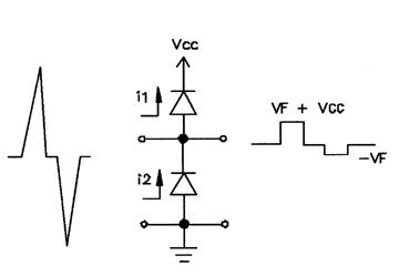
Thanks to everyone for the informative answers. Here is the over-voltage protection circuit that Iv decided on. I plan to use schottky diodes for greater precision.

During a negative voltage transient, the bottom diode will conduct, thereby clamping the voltage to one diode drop below ground. During a positive voltage transient, the top diode will be forward biased, thus conducting the surge to the power rail.

From: http://www.conformity.com/artman/publish/printer_116.shtml
alt text

\$\endgroup\$
3
  • 1
    \$\begingroup\$ Which micro are you using? \$\endgroup\$ Commented Oct 25, 2010 at 13:16
  • 1
    \$\begingroup\$ What are the specs of your integrated ADC? I can guarantee that you'll get far better results with a discrete ADC. \$\endgroup\$ Commented Oct 25, 2010 at 14:30
  • \$\begingroup\$ Im using an P89LPC938 which has a 10-bit ADC. I have considered using a discrete ADC and I may do if necessary, but for the moment though I'm concentrating my efforts on getting the signal conditioning right, if it turns out that the micros ADC doesn't cut it, it shouldn't be too difficult to change... \$\endgroup\$
    – volting
    Commented Oct 25, 2010 at 14:40

4 Answers 4

5
\$\begingroup\$

OpenCircuits input protection discussion:

http://www.opencircuits.com/Input_protection

It basically boils down to some resistors to limit current and a zener to limit voltage with a couple of capacitors thrown in.

\$\endgroup\$
2
2
\$\begingroup\$

In this scenario you would usually use a combination of zeners and diodes to protect the ADC input from excessive voltages. You would also avoid letting even the overload voltage approach the maximum input voltage (e.g. have your meter measure 0-2V and set the overload at 3V for a 3.3V supply.)

\$\endgroup\$
0
2
\$\begingroup\$

Here is another solution that may be more expensive and take more space, but it is something to consider.

You could use an opamp and set the rails of the opamp to be the same rails as the microcontroller. This will prevent the opamp from ever outputting more then what the microcontroller can handle. Then you can use the pot to control the gain of the opamp.

\$\endgroup\$
7
  • \$\begingroup\$ As a note though, opamps still can have issues with over voltage. \$\endgroup\$
    – Kellenjb
    Commented Oct 25, 2010 at 18:18
  • \$\begingroup\$ +1 for an alternative. What op-amp configuration do you suggest, I was thinking two inverting configs in succession, one to deal with gain (+/-) (i.e so that I can either divide or multiply the input voltage), and another to cancel the inversion of the first, or? \$\endgroup\$
    – volting
    Commented Oct 25, 2010 at 18:27
  • \$\begingroup\$ What really makes this solution difficult to implement is that you may not have a negative voltage rail available to you. \$\endgroup\$
    – Kellenjb
    Commented Oct 25, 2010 at 18:49
  • \$\begingroup\$ Ya your right... I forgot that Id need a negative supply, Doh!! In that case Its probably not worth the hassle. \$\endgroup\$
    – volting
    Commented Oct 25, 2010 at 19:08
  • \$\begingroup\$ Nah, I didn't think it was, just wanted to throw that out as an option if you happened to be creating a more sophisticated meter. \$\endgroup\$
    – Kellenjb
    Commented Oct 25, 2010 at 19:09
0
\$\begingroup\$

if your multimeter supports differential inputs, i.e. +-10V or -+10V, you also need two zeners back to back, study the schematics of old multimeters like the 8842A and 34401 to learn more

\$\endgroup\$

Your Answer

By clicking “Post Your Answer”, you agree to our terms of service and acknowledge you have read our privacy policy.

Not the answer you're looking for? Browse other questions tagged or ask your own question.